IR3220STR International Rectifier, IR3220STR Datasheet
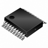
IC H-BRIDGE 45V 6A 20SOIC

IR3220STR

Manufacturer Part Number
IR3220STR
Description
IC H-BRIDGE 45V 6A 20SOIC
Manufacturer
International Rectifier
Type
H Bridger
Datasheet

Specifications of IR3220STR

Input Type
Non-Inverting
Number Of Outputs
4
On-state Resistance
11 mOhm
Current - Output / Channel
2A
Current - Peak Output
15A
Voltage - Supply
8 V ~ 28 V
Operating Temperature
-40°C ~ 150°C
Mounting Type
Surface Mount
Package / Case
20-SOIC (7.5mm Width)
Lead Free Status / RoHS Status
Contains lead / RoHS non-compliant

Available stocks

Company
Part Number
Manufacturer
Quantity
Price
Part Number:
IR3220STRPBF
Manufacturer:
IR
Quantity:
20 000
The IR3220S is a fully protected dual high side switch I.C that
integrates an H–bridge motor controller with two very efficient
high side MOSFETs in a single 20-pin package. The IR3220S
combines with the two low side IRF7484Q MOSFETs as few as
10 external passive components to provide a complete, fully op-
erational and fully protected H-bridge control actuator with for-
ward, reverse, braking and non-braking modes without the need
of a micro-controller.
Functional Description
The high side switches provide the direction capability and the H-
bridge protection. The low side MOSFETs bring the flexibility by
offering the high frequency switching ability. Therefore, crude
start-up of the motor is avoided and replaced by a smooth and
stress-less speed ramp-up.
The IR3220S features shoot-through protection for each leg, H-
bridge logic control, soft-start sequence and over-current / over-
temperature shutdown protections. Two input signals (IN1 & IN2)
select the operating modes while the PWM soft-start sequence
cycles the corresponding active low side MOSFET in order to
limit the motor in-rush current. The soft-start sequence is pro-
grammed by an RC time constant and reset itself automatically.
Thanks to the inner PWM oscillator, the IR3220S can also be
the final stage of an overall torque or speed loop. If needed, an
external clock may force the H-bridge switching operation. This
can be combined with low frequency PWM operation through
the IN1(2) inputs.
The IR3220S is a Co-pack IPS product offering very low Rds(on)
and a high level of functionality and protection. Its open architec-
ture and programmability helps the designer to optimize each
motor drive upon the application requirements at a very low cost.
For automotive actuators, the motor is kept shorted even during
the low consumption sleep mode. Shoot-through protection, over-
temperature & over-current shutdowns, self-adaptive dead-time
and PWM circuitries are described in details in the AN 1032
Application Note. A general purpose method to help rating the
soft-start sequence as well as layout and thermal considerations
are also covered. Finally, a 6A DC motor actuator with a PCB
size down to 1 Inch² is suggested in the document.
www.irf.com
FULLY PROTECTED H-BRIDGE FOR D.C. MOTOR
Features
Packages
Programmable PWM In-rush
Current Limitation (e.g 18A)
6 A Continuous Current Capability
without Heat Sink (2 x 13 m )
Over-Temperature (165 °C) and
Over-Current (30A) Protections
20 kHz PWM Oscillator Embedded
Low & High Frequency Switching
Operation (self adaptive dead-time)
Easy Speed / Torque Control
(analog duty cycle input)
Braking / Non-Braking Modes
Sleep Mode (braking) for
Automotive Actuator
Data Sheet No.PD60180-C
8-Lead SOIC
IRF7484Q
20-Lead SOIC
(wide body)
IR3220S
1

Related parts for IR3220STR

IR3220STR Summary of contents

Page 1

FULLY PROTECTED H-BRIDGE FOR D.C. MOTOR The IR3220S is a fully protected dual high side switch I.C that integrates an H–bridge motor controller with two very efficient high side MOSFETs in a single 20-pin package. The IR3220S combines with the ...

Page 2

IR3220S Functional Block Diagram Soft Start duty cycle VCC IN 1 Over current Shoot-through protection Low Side G 1 Driver 50 Thanks to the self-adaptive dead-time circuitry, the low side MOSFET of each leg is driven in the opposite phase ...

Page 3

Soft-Start Sequence IN1 (IN2) Vss+ SS Vss- M1-M2 Duty cycle modulation follows SS voltage (M2-M1) Tss ( approximately 1 time constant ) Truth Table IN1 IN2 MODES L L Stand-by with braking - sleep mode Forward ...

Page 4

IR3220S Typical Connection + Bat. VCC Vrc gate Mosfet C Electrical stop IN1 IN2 SS M1 Soft-Start sequence M2 Braking Mode (M1 & M2 grounded) Motor Current 4 Gnd ...

Page 5

The PWM generator is based saw-tooth oscillator. The soft-start sequence takes advantage of the RC charge profile in order to perform a smooth duty cycle variation. When the SS pin is below 1.2V, no PWM signal is ...

Page 6

IR3220S In addition, the soft-start sequence pro- vides a smooth motion of the window. Torque or speed controls are also achievable without any micro-control- ler. With a few additional components, the IR 3220S can be the ‘’power stage‘’ ...

Page 7

Absolute Maximum Ratings Absolute maximum ratings indicate sustained limits beyond which damage to the device may occur. All voltage param- eters are referenced to Gnd lead. (T Ambient = 25 Symbol Parameter V m1 (2) Maximum M1 (M2) voltage (active ...

Page 8

IR3220S Recommended Operating Conditions These values are given for a quick design. For operation outside these conditions, please consult the application notes. Symbol Parameter V cc Continuous Vcc voltage (2) V in1 (2) High level IN 1 (IN 2) input ...

Page 9

Switching Electrical Characteristics 14V, Resistive Load = 3 Symbol Parameter Td on Turn-on delay time T r1 Rise time to Vout = Vcc -5V Tr2 Rise time from the end of Tr1 to V ...

Page 10

IR3220S Lead Definitions Vcc Positive power supply M1 Motor 1 output ( high side source - leg Motor 2 output ( high side source - leg Gate 1 drive output ( low side gate ...

Page 11

IN1 (2) I M1( Vcc ) M1( clamp ( see IPS Appl . Notes to evaluate power dissipation ) Figure 1 - Active clamp waveforms IN 1(2) Vcc 90% Vcc - (2) ...

Page 12

IR3220S 5 ----- IN1h( IN1l( -IN1(2) hysteresis Figure 5 - IN1 (2) thresholds ( ...

Page 13

25° 150° 0,0 0,2 0,4 0,6 0,8 Figure 9 - Body diode : Ids (A) vs Vds ( -50 - ...

Page 14

IR3220S 100 10 1 0,1 rth std footprint 0,01 o Figure 13 - Transient Rth ( C/W) vs Time (S) Case Outline - 8 Lead SOIC 14 1000 100 10 1,E-06 1,E-05 1,E-04 1,E-03 1,E-02 1,E-01 Figure 14 - Isd ...

Page 15

Case Outline IR WORLD HEADQUARTERS: 233 Kansas St., El Segundo, California 90245 Tel: (310) 252-7105 WWW.IRF.COM 20 Lead SOIC (wide body) Data and specifications subject to change without notice. 9/18/2003 IR3220S (MS-013AC) 01-3080 00 15 ...

Related keywords