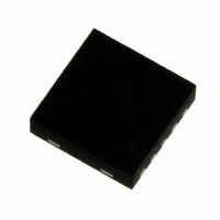
A3901SEJTR-T Allegro Microsystems Inc, A3901SEJTR-T Datasheet

A3901SEJTR-T
Specifications of A3901SEJTR-T
Available stocks
Related parts for A3901SEJTR-T
A3901SEJTR-T Summary of contents
Page 1
Dual Full Bridge Low Voltage Motor Driver Features and Benefits ▪ Low R outputs DS(on) ▪ Full- and half-stepping capability ▪ Small package ▪ Forward, reverse, and brake modes for DC motors ▪ Sleep mode with zero current drain ▪ ...
Page 2
... A3901 Part Number A3901SEJTR-T Parameter Load Supply Voltage Output Current per Channel* Logic Input Voltage Range Junction Temperature Storage Temperature Range Operating Temperature Range *Output current rating may be limited by duty cycle, ambient temperature, and heat sinking. Under any set of conditions, do not exceed the specified current rating or a junction temperature of 150° ...
Page 3
A3901 10 µ IN1 IN2 IN3 IN4 Number – Dual Full Bridge Low Voltage Motor Driver Functional Block Diagram VBB TSD Control Logic and Gate Drive PAD GND ...
Page 4
A3901 ELECTRICAL CHARACTERISTICS at T Characteristics Output On Resistance Clamp Diode Motor Supply Current Logic Input Voltage Logic Input Current Input Voltage Hysteresis Propagation Delay Crossover Delay Thermal Shut Down Temperature Thermal Shut Down Hysteresis THERMAL CHARACTERISTICS Characteristics Package Thermal ...
Page 5
A3901 1 INx Stepper Motor IN1 IN2 IN3 Motor (Dual) IN1 or ...
Page 6
A3901 Output On Resistance versus Load Supply Voltage I = 100 mA OUT 4.00 3.50 3.00 2.50 2.00 1.50 1.00 0.50 2.5 3.0 3.5 4.0 V (V) BB Output On Resistance versus Output Current 3.50 ...
Page 7
A3901 Device Operation. The A3901 is a dual full-bridge low voltage motor driver capable of operating one stepper motor two DC motors. MOSFET output stages substantially reduce the voltage drop and the power dissipation of the outputs ...
Page 8
A3901 IN1 IN2 GND IN3 IN4 IOUT1-2 IOUT3-4 IOUT1-2 IOUT3-4 Dual Full Bridge Low Voltage Motor Driver Application Information TSD CONTROL LOGIC/ GATE DRIVE Figure 4a. Typical stepper motor control application IN1 IN2 IN3 IN4 +V /R ...
Page 9
A3901 IN1 IN2 GND IN3 IN4 Figure 5. Typical dual DC motor control application. Either IN1 or IN2 can be used to drive OUT1 and OUT2. Either IN3 or IN4 can be used to drive OUT3 and OUT4. IN1 IN2 ...
Page 10
A3901 IN1/3 IN2 motor +(V –V )/R BB BEMF motor IOUT1-2/3-4 0A –(V –V )/R BB BEMF motor – motor IN1/3 IN2/4 +I REG IOUT1-2/3-4 0A –I REG Figure 8. External PWM current control in ...
Page 11
A3901 D 11X 0.08 C 0.40 Copyright ©2005,2007, Allegro MicroSystems, Inc. The products described here are manufactured under one or more U.S. patents or U.S. patents pending. Allegro MicroSystems, Inc. reserves the right to make, from time to time, such ...


