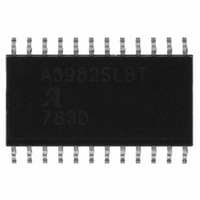
A3982SLBTR-T Allegro Microsystems Inc, A3982SLBTR-T Datasheet

A3982SLBTR-T
Specifications of A3982SLBTR-T
A3982SLBTR-T
Available stocks
Related parts for A3982SLBTR-T
A3982SLBTR-T Summary of contents
Page 1
DMOS Stepper Motor Driver with Translator Features and Benefits ▪ Low R outputs DS(on) ▪ Automatic current decay mode detection/selection ▪ Mixed and Slow current decay modes ▪ Synchronous rectification for low power dissipation ▪ Internal UVLO and thermal shutdown ...
Page 2
... Internal synchronous rectification control circuitry is provided to improve power dissipation during PWM operation. Selection Guide Part Number A3982SLB-T 31 pieces per tube A3982SLBTR-T 1000 pieces per reel *Contact Allegro for additional packing options Absolute Maximum Ratings Characteristic Load Supply Voltage Logic Input Voltage ...
Page 3
A3982 VREG VDD Current Regulator REF DAC STEP DIR RESET Translator MS1 ENABLE DAC V REF DMOS Stepper Motor Driver with Translator Functional Block Diagram 0.22 μF CP1 ROSC OSC DMOS Full Bridge PWM Latch Blanking Mixed Decay Gate Drive ...
Page 4
A3982 ELECTRICAL CHARACTERISTICS Characteristics Output Drivers Load Supply Voltage Range Logic Supply Voltage Range Output On Resistance Body Diode Forward Voltage Motor Supply Current Logic Supply Current Control Logic Logic Input Voltage Logic Input Current Input Hysteresis Blank Time Fixed ...
Page 5
A3982 THERMAL CHARACTERISTICS Characteristic Package Thermal Resistance *Additional thermal information available on Allegro Web site. DMOS Stepper Motor Driver with Translator Symbol Test Conditions* One-layer PCB, one-sided with copper limited to solder pads One-layer PCB, two-sided with copper limited to ...
Page 6
A3982 STEP MS1, RESET, or DIR STEP minimum, HIGH pulse width STEP minimum, LOW pulse width Setup time, input change to STEP Hold time, input change to STEP Figure 1. Logic Interface Timing Diagram DMOS Stepper Motor Driver with Translator ...
Page 7
A3982 The A3982 is a complete stepper Device Operation. motor driver with a built-in translator for easy operation with minimal control lines designed to operate bipolar stepper motors in full- and half-step modes. The currents in each of ...
Page 8
A3982 is determined by the selection of an external resistor con- nected from the ROSC timing pin to ground. If the ROSC pin is tied to an external voltage > then t 30 μs. The ROSC pin can ...
Page 9
A3982 STEP 100.00 70.71 Phase 1 I OUT1A 0.00 Direction = H (%) –70.71 –100.00 100.00 70.71 Phase 2 I OUT2A 0.00 Direction = H (%) –70.71 –100.00 Figure 2. Decay Mode for Full-Step Increments DMOS Stepper Motor Driver with ...
Page 10
A3982 Pin List Table Name OUT2A SENSE2 VBB2 OUT2B ENABLE PGND PGND VREG RESET ROSC STEP PGND PGND 1OUT1B VBB1 SENSE1 OUT1A DMOS Stepper Motor Driver with Translator Description DMOS Full Bridge 2 Output A Sense resistor for Bridge 2 ...
Page 11
A3982 15.40±0. 24X 0.10 C 0.41 ±0.10 1.27 For reference only Pins 6 and 7, and 18 and 19 internally fused Dimensions in millimeters (Reference JEDEC MS-013 AD) Dimensions exclusive of mold flash, gate burrs, and ...


