U211B-MFPG3Y Atmel, U211B-MFPG3Y Datasheet - Page 6

U211B-MFPG3Y
Manufacturer Part Number
U211B-MFPG3Y
Description
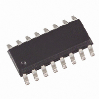
IC PHASE CONTROL TACHO 16SOIC
Manufacturer
Atmel
Datasheet
1.U211B-MFPG3Y.pdf
(29 pages)
Specifications of U211B-MFPG3Y
Applications
AC Motor Controller
Number Of Outputs
1
Current - Output
7.5mA
Voltage - Supply
14.6 V ~ 16.6 V
Operating Temperature
-10°C ~ 100°C
Mounting Type
Surface Mount
Package / Case
16-SOIC (3.9mm Width)
Mounting Style
SMD/SMT
Lead Free Status / RoHS Status
Lead free / RoHS Compliant
Voltage - Load
-
Lead Free Status / Rohs Status
Compliant
7. Frequency-to-voltage Converter
6
U211B
The internal frequency-to-voltage converter (f/V converter) generates a DC signal on pin 10
which is proportional to the rotational speed, using an AC signal from a tacho generator or a
light beam whose frequency is in turn dependent on the rotational speed. The high-impedance
input pin 8 compares the tacho voltage to a switch-on threshold of typically –100 mV. The
switch-off threshold is –50 mV. The hysteresis guarantees very reliable operation even when
relatively simple tacho generators are used.
The tacho frequency is given by:
where:
The converter is based on the charge pumping principle. With each negative half-wave of the
input signal, a quantity of charge determined by C
by C
charge transfer voltage of V
k = G
The analog output voltage is given by
V
The values of C
mum output voltage V
approximately 6.7 k . To obtain good linearity of the f/V converter, the time constant resulting
from R
for the highest possible input frequency. The amount of remaining ripple on the output voltage
on pin 10 is dependent on C
The ripple V
will then also be reduced.
The value of this capacitor should be chosen to fit the particular control loop where it is going
to be used.
f
G
V
O
=
i
O
= k
I
------ -
I
10
----- -
60
6
9
n
i
=
at the converter output on pin 10. The conversion constant is determined by C
i
and C
G
------------------------------------ -
=
C
f
p (Hz)
i
5
8.3
V
C
5
O
R
ch
should be considerably less (1/5) than the time span of the negative half-cycle
6
6
can be reduced by using larger values of C
5
and C
C
V
5
ch
n
p
6
O
must be such that for the highest possible input frequency, the maxi-
does not exceed 6V. While C
ch
5
, C
, R
= Revolutions per minute
= Number of pulses per revolution
6
6
and the internal charge amplification.
(pin 10) and the internally adjusted charge transfer gain.
5
is internally amplified and then integrated
5
is charging up, the R
6
. However, the increasing speed
4752B–INDCO–09/05
i
on pin 9 is
5
, its


