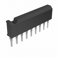
BA6283N Rohm Semiconductor, BA6283N Datasheet

BA6283N
Specifications of BA6283N
Available stocks
Related parts for BA6283N
BA6283N Summary of contents
Page 1
... Reversible motor driver BA6283N / BA6955N The BA6283N and BA6955N are reversible-motor drivers with a maximum output current of 1.0A. Two logic inputs allow four output modes: forward, reverse, stop (standby), and brake. The built-in power save circuit suppresses current consumption in the motor stop mode. ...
Page 2
... Motor driver ICs ! ! ! ! Block diagram BA6283N TSD 1 2 OUT2 R NF BA6955N CONTROL LOGIC OUT1 V GND CONTROL LOGIC TSD POWER SAVE GND R OUT2 BA6283N / BA6955N POWER SAVE GND OUT1 V M ...
Page 3
... Motor output 6 R Output GND, for connecting resistor for output current detection NF Motor output 7 OUT1 8 V Motor power supply Input / Output circuit OUT2 OUT1 R NF Fig.1 BA6283N / BA6955N Functions Functions 12k 4.7k 20k GND 11k 11k 10k Resistances are typical values Fig.2 ...
Page 4
... Input/Output truth table about the output mode. Circuit current : Input high level voltage, Input low level voltage : ∗Refer to the Input/Output truth table about the output mode. Input high level current : =2V BA6283N / BA6955N =9V) M Conditions − − =2.0V IN =200mA at V =2V IR ...
Page 5
... High to Low Level output pins High and High. Putting F and R both High result in the brake mode. In this mode Mode L Forward H Reverse L Brake Standby is a Motor Power supply terminal. M BA6283N / BA6955N is Low, and from OUT2 to OUT1 IN and R are both Low, both OUT1 and IN IN ...
Page 6
... Ground (GND Attached the current detection resistors at the R attached the electronic governor, the speed-variable reversible motors can be constructed Application example BA6238N TSD M terminal, the current flowing in the motor can be detected. Also NF CONTROL LOGIC V CC CONTROL IC Fig.6 BA6283N / BA6955N POWER SAVE LOGIC ...
Page 7
... Depending on the ambient conditions, environment, or motor characteristics, the back-rush voltage may fluctuate. Be sure to confirm that the back-rush voltage will not adversely affect the operation of the IC. CONTROL LOGIC TSD POWER SAVE M LOGIC CONTROL IC Fig.7 voltage is not applied to the IC. Similarly, when V CC and within the guaranteed range for the electrical CC BA6283N / BA6955N CC ...
Page 8
... To eliminate motor noise, connect a capacitor between OUT1 and GND and between OUT2 and GND. Alternatively, connect a capacitor between OUT1 and OUT2, and also a diode between OUT1 and GND and between OUT2 and GND (see the figure below). OUT1 OUT2 OUT2 OUT1 BA6283N / BA6955N ...
Page 9
... SIP9 Curcuit current 2 Inputs Curcuit current 1 Inputs SUPPLY VOLTAGE : V (V) CC Fig.9 Circuit current vs. power supply voltage BA6955N 2.8±0 0.6 0.3±0.1 0.8 1.3 BA6283N / BA6955N V CC −0 Inputs −1.0 Outputs : OUT1 = =9V M −1 −2 −2 −3 0.2 0.4 0.6 0.8 1 ...


