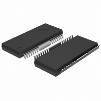
BA6664FM Rohm Semiconductor, BA6664FM Datasheet - Page 14

BA6664FM
Manufacturer Part Number
BA6664FM
Description
IC MOTOR DRIVER CD/DVD HSOP-M28
Manufacturer
Rohm Semiconductor
Datasheet
1.BA6664FM.pdf
(18 pages)
Specifications of BA6664FM
Applications
DC Motor Driver, 3 Phase
Number Of Outputs
1
Current - Output
1.3A
Voltage - Load
3 V ~ 14 V
Voltage - Supply
4.5 V ~ 5.5 V
Operating Temperature
-20°C ~ 75°C
Mounting Type
Surface Mount
Package / Case
28-HSOP
Lead Free Status / RoHS Status
Lead free / RoHS Compliant
Available stocks
Company
Part Number
Manufacturer
Quantity
Price
Company:
Part Number:
BA6664FM
Manufacturer:
ROHM
Quantity:
1 670
Part Number:
BA6664FM
Manufacturer:
ROHM/罗姆
Quantity:
20 000
Company:
Part Number:
BA6664FM-E2
Manufacturer:
FUJI
Quantity:
400
Part Number:
BA6664FM-E2
Manufacturer:
ROHM/罗姆
Quantity:
20 000
●Reverse Rotation Detection Function
●FR Signal Output (BA6859AFP-Y, BA6664FM)
●Brake Mode Change (BA6664FM, BD6671FM)
●Short Brake (BA6859AFP-Y, BA6664FM)
●Hall Input
BA6859AFP-Y,BA6664FM,BD6671FM
© 2010 ROHM Co., Ltd. All rights reserved.
www.rohm.com
Fig. 13 shows the construction of the reverse rotation detection circuit.
・Forward rotation (EC<ECR)
・Reverse rotation (EC>ECR)
FR output signal pin outputs the FR signal of low(L) or high(H) after detecting the motor rotation direction.
By applying high-level voltage to the BR pin, the brake mode for the following condition can be changed: EC > ECR.
When the BR pin is set to high level and used in short-brake mode, open the SB pin.
The BR pin has a temperature characteristics of approximately -5 mV/℃. Use the BR pin within the permissible input range.
The Hall element allows both serial and parallel connections.
Fig. 9 shows the phase relation of the H2+ and H3+ Hall input signals,
in which case the reverse rotation detection circuit will not work.
The phase relation of the H2+ and H3+ signals are opposite to that when the motor is rotating in the forward direction.
Therefore, the reverse rotation detection circuit operates, and the output is turned off and open.
H2
H2-
H3
H3-
BR
Motor rotation direction
+
+
Parallel Connection
H3
15-pin (Hall Bias)
OFF
ON
+
-
+
-
EC
ECR
H2
Reverse
Forward
H
L
A
V
OFF
C C
O
ON
H1
CK
D
+
-
D-FF
Fig.14
Fig.13
A
Fig.15
OFF
Q
ON
Forward rotation
Forward rotation
MOTOR
EC<ECR
Serial Connection
15-pin (Hall Bias)
A
H:OUTPUT.OPEN
(HIGH-IMPEDANCE)
H3
H1
H2
V
C C
When the short-brake pin is set to high level, as shown in Fig.18, the output
transistor (3-phase) on the high side will be turned off and the output transistor
(3-phase) on the low side will be turned on. The short brake pin has a
temperature characteristic of approximately -5 mV/℃. Keep the input voltage
range (see Fig12) in mind.
FR signal output
“H”
“L”
Reverse rotation brake
Set the Hall input voltage between 1.0 and 4.0 V. Compute the
resistance between the VH and VCC pins in consideration of the
flowing current of the Hall device.
14/17
Short brake
EC>ECR
When the motor rotates in the reverse direction, the reverse rotation
detection function will operate and the output will be in an open state.
Actual motor rotation at reverse detection
The motor rotates in a reverse direction with inertial force.
EC < ECR: Forward torque (forward rotation)
EC > ECR: Deceleration (forward rotation)
Stop
Technical Note
2010.06 - Rev.A


