A3977SLP-T Allegro Microsystems Inc, A3977SLP-T Datasheet - Page 7
A3977SLP-T
Manufacturer Part Number
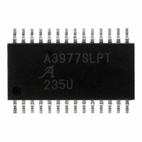
A3977SLP-T
Description
IC MOTOR DRIVER PWM DUAL 28-TSSO
Manufacturer
Allegro Microsystems Inc
Specifications of A3977SLP-T
Applications
Stepper Motor Driver
Number Of Outputs
1
Current - Output
±2.5A
Voltage - Load
8 V ~ 35 V
Voltage - Supply
3 V ~ 5.5 V
Operating Temperature
-20°C ~ 85°C
Mounting Type
Surface Mount
Package / Case
28-TSSOP Exposed Pad, 28-eTSSOP, 28-HTSSOP
Operating Current
12mA
Operating Temperature Classification
Commercial
Package Type
TSSOP EP
Operating Supply Voltage (min)
3V
Operating Supply Voltage (typ)
5V
Operating Supply Voltage (max)
5.5V
Lead Free Status / RoHS Status
Lead free / RoHS Compliant
Other names
620-1079


A3977
Device Operation. The A3977 is a complete microstep-
ping motor driver with built in translator for easy operation
with minimal control lines. It is designed to operate bipolar
stepper motors in full-, half-, quarter- and eighth-step
modes. The current in each of the two output full-bridges,
all N-channel DMOS, is regulated with fi xed off-time
pulse-width modulated (PWM) control circuitry. The full-
bridge current at each step is set by the value of an external
current sense resistor (R
the DACs output voltage controlled by the output of the
translator.
and phase current polarity to initial home state (see fi gures
for home-state conditions), and sets the current regula-
tor for both phases to mixed-decay mode. When a step
command signal occurs on the STEP input the translator
automatically sequences the DACs to the next level (see
table 2 for the current level sequence and current polarity).
The microstep resolution is set by inputs MS
as shown in table 1. If the new DAC output level is lower
than the previous level the decay mode for that full-bridge
will be set by the PFD input (fast, slow, or mixed decay).
If the new DAC level is higher or equal to the previous
level then the decay mode for that full-bridge will be slow
decay. This automatic current-decay selection will improve
microstepping performance by reducing the distortion of
the current waveform due to the motor BEMF.
Reset Input (RESET). The RESET input (active low)
sets the translator to a predefi ned home state (see fi gures
for home state conditions) and turns off all of the DMOS
outputs. The HOME output goes low and all STEP inputs
are ignored until the RESET input goes high.
Home Output (HOME). The HOME output is a logic
output indicator of the initial state of the translator. At
power up the translator is reset to the home state (see fi g-
ures for home state conditions).
At power up, or reset, the translator sets the DACs
S
), a reference voltage (V
Microstepping DMOS Driver with Translator
1
and MS
Functional Description
REF
), and
2
Step Input (STEP). A low-to-high transition on the
STEP input sequences the translator and advances the
motor one increment. The translator controls the input to
the DACs and the direction of current fl ow in each wind-
ing. The size of the increment is determined by the state of
inputs MS
Microstep Select (MS
MS1 and MS
table 1. Changes to these inputs do not take effect until the
STEP command (see fi gure).
Direction Input (DIR). The state of the DIRECTION
input will determine the direction of rotation of the motor.
Internal PWM Current Control. Each full-bridge is
controlled by a fi xed off-time PWM current-control cir-
cuit that limits the load current to a desired value (I
Initially, a diagonal pair of source and sink DMOS outputs
are enabled and current fl ows through the motor winding
and R
equals the DAC output voltage, the current-sense compara-
tor resets the PWM latch, which turns off the source driver
(slow-decay mode) or the sink and source drivers (fast- or
mixed-decay modes).
selection of R
transconductance function approximated by:
rent-sense comparator in precise steps (see table 2 for %
I
on the SENSE terminal is not exceeded. For full-step
mode, V
V
other modes V
TRIP
DD
The maximum value of current limiting is set by the
The DAC output reduces the V
It is critical to ensure that the maximum rating (0.5 V)
, because the peak sense value is 0.707 x V
max at each step).
S
. When the voltage across the current-sense resistor
I
REF
TRIP
1
and MS
can be applied up to the maximum rating of
2
= (% I
S
select the microstepping format per
REF
and the voltage at the V
should not exceed 4 V.
I
TRIP
2
TRIP
(see table 1).
max = V
max/100) x I
115 Northeast Cutoff
1.508.853.5000; www.allegromicro.com
Allegro MicroSystems, Inc.
Worcester, Massachusetts 01615-0036 U.S.A.
1
and MS
REF
REF
2
/8R
). Input terminals
TRIP
output to the cur-
REF
S
max
input with a
REF
/8. In all
TRIP
).
7
Related parts for A3977SLP-T
Image
Part Number
Description
Manufacturer
Datasheet
Request
R


Part Number:
Description:
IC, HALL EFFECT SENSOR, Linear, SOIC-8
Manufacturer:
Allegro Microsystems Inc
Datasheet:
Part Number:
Description:
IC, HALL EFFECT SENSOR, Linear, SOIC-8
Manufacturer:
Allegro Microsystems Inc
Datasheet:
Part Number:
Description:
IC, HALL EFFECT SENSOR, Linear, SOIC-8
Manufacturer:
Allegro Microsystems Inc
Datasheet:

Part Number:
Description:
IC SWITCH INTERFACE 2CHAN 8-SOIC
Manufacturer:
Allegro Microsystems Inc
Datasheet:

Part Number:
Description:
IC SMOKE DETECTOR ION 16-DIP
Manufacturer:
Allegro Microsystems Inc
Datasheet:
Part Number:
Description:
IC SMOKE DETECTOR ION 16-DIP
Manufacturer:
Allegro Microsystems Inc
Datasheet:
Part Number:
Description:
IC SMOKE DETECTOR ION 16-DIP
Manufacturer:
Allegro Microsystems Inc
Datasheet:
Part Number:
Description:
IC SMOKE DETECTOR PHOTO 16-DIP
Manufacturer:
Allegro Microsystems Inc
Datasheet:
Part Number:
Description:
IC SMOKE DETECTOR ION 16-DIP
Manufacturer:
Allegro Microsystems Inc
Datasheet:
Part Number:
Description:
IC SMOKE DETECTOR PHOTO 16-DIP
Manufacturer:
Allegro Microsystems Inc
Datasheet:
Part Number:
Description:
IC SMOKE DETECTOR PHOTO 16-DIP
Manufacturer:
Allegro Microsystems Inc
Datasheet:
Part Number:
Description:
IC SMOKE DETECTOR ION 16-DIP
Manufacturer:
Allegro Microsystems Inc
Datasheet:
Part Number:
Description:
IC SMOKE DETECTOR PHOTO 16-SOIC
Manufacturer:
Allegro Microsystems Inc
Datasheet:

Part Number:
Description:
IC LED DRIVER HIGH BRIGHT 16-QFN
Manufacturer:
Allegro Microsystems Inc
Datasheet: