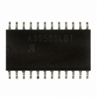
A3958SLBTR-T Allegro Microsystems Inc, A3958SLBTR-T Datasheet - Page 6

A3958SLBTR-T
Manufacturer Part Number
A3958SLBTR-T
Description
IC MOTOR DRIVER PWM FULL 24-SOIC
Manufacturer
Allegro Microsystems Inc
Datasheet
1.A3958SB.pdf
(11 pages)
Specifications of A3958SLBTR-T
Applications
PWM Motor Driver
Number Of Outputs
1
Current - Output
±2A
Voltage - Load
20 V ~ 50 V
Voltage - Supply
4.5 V ~ 5.5 V
Operating Temperature
-20°C ~ 85°C
Mounting Type
Surface Mount
Package / Case
24-SOIC (7.5mm Width)
Lead Free Status / RoHS Status
Lead free / RoHS Compliant
Other names
620-1135-2
A3958SLBTR-T
A3958SLBTR-T
Available stocks
Company
Part Number
Manufacturer
Quantity
Price
Part Number:
A3958SLBTR-T-XS
Manufacturer:
ALLEGRO/雅丽高
Quantity:
20 000
A3958
Serial Interface. The A3958 is controlled via a 3-wire
(clock, data, strobe) serial port. The programmable
functions allow maximum fl exibility in confi guring the
PWM to the motor drive requirements. The serial data is
clocked in starting with D19.
D0 – D1 Blank Time. The current-sense comparator is
blanked when any output driver is switched on, according
to the table below. f
D2 – D6 Fixed-Off Time. A fi ve-bit word sets the fi xed-
off time for internal PWM current control. The off time is
defi ned by
where N = 0 … 31
For example, with an oscillator frequency of 4 MHz, the
off time will be adjustable from 1.75 μs to 63.75 μs in
increments of 2 μs.
D10 Fast Decay Time MSB
D12 Sync. Rect. Enable
D13 External PWM Mode
D14 Enable
D15 Phase
D16 Reference Range Select
D17 Internal PWM Mode
D18 Test Use Only
D19 Sleep Mode
D11 Sync. Rect. Mode
Bit
D0
D1
D2
D3
D4
D5
D6
D7
D8
D9
D1
0
0
1
1
t
off
Function
Blank Time LSB
Blank Time MSB
Off Time LSB
Off Time Bit 1
Off Time Bit 2
Off Time Bit 3
Off Time MSB
Fast Decay Time LSB
Fast Decay Time Bit 1
Fast Decay Time Bit 2
osc
= (8[1 + N]/f
D0
is the oscillator input frequency.
0
1
0
1
Blank Time
osc
12/f
24/f
4/f
6/f
) - 1/f
osc
osc
osc
osc
osc
FUNCTIONAL DESCRIPTION
DMOS Full-Bridge PWM Motor Driver
D7 – D10 Fast Decay Time. A four-bit word sets the
fast-decay portion of the fi xed-off time for the internal
PWM control circuitry. This will only have impact if the
mixed-decay mode is selected (via bit D17 and the MODE
input terminal). For t
operate in the fast-decay mode. The fast decay portion is
defi ned by
where N = 0 … 15
For example, with an oscillator frequency of 4 MHz, the
fast decay time will be adjustable from 1.75 μs to
31.75 μs in increments of 2 μs.
D11 Synchronous Rectifi cation Mode. The active
mode prevents reversal of load current by turning off
synchronous rectifi cation when a zero current level is
detected. The passive mode will allow reversal of current
but will turn off the synchronous rectifi er circuit if the load
current inversion ramps up to the current limit set by
V
D12 Synchronous Rectifi cation Enable.
D13 External PWM Decay Mode. Bit D13 determines
the current-decay mode when using ENABLE chopping
for external PWM current control.
D14 Enable Logic. Bit D14, in conjunction with
ENABLE, determines if the output drivers are in the
chopped (OFF)(ENABLE = D14) or ON (ENABLE ≠
D14) state.
REF
/R
S
.
D12
ENABLE
D13
D11
0
1
t
0
1
0
1
fd
0
1
0
1
= (8[1 + N]/f
fd
Synchronous Rect.
Disabled
Enabled
115 Northeast Cutoff
1.508.853.5000; www.allegromicro.com
Allegro MicroSystems, Inc.
Worcester, Massachusetts 01615-0036 U.S.A.
> t
Mode
Active
Passive
Mode
Fast
Slow
off
, the device will effectively
D14
0
0
1
1
osc
) - 1/f
Chopped
Chopped
Mode
On
On
osc
5


