SA07 Cirrus Logic Inc, SA07 Datasheet - Page 6
SA07
Manufacturer Part Number
SA07
Description
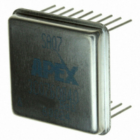
AMP PWM SW 40V 5A 18P DIP EL
Manufacturer
Cirrus Logic Inc
Series
Apex Precision Power™r
Datasheet
1.SA07.pdf
(7 pages)
Specifications of SA07
Mfg Application Notes
SAxx App Note 34
Applications
DC Motor Controller
Number Of Outputs
1
Current - Output
5A
Voltage - Load
5 V ~ 40 V
Voltage - Supply
10 V ~ 16 V
Operating Temperature
-55°C ~ 125°C
Mounting Type
Through Hole
Package / Case
18-DIP
For Use With
598-1457 - EVALUATION KIT FOR SA07
Lead Free Status / RoHS Status
Lead free / RoHS Compliant
Other names
598-1453
SA07
SA07
Available stocks
Company
Part Number
Manufacturer
Quantity
Price

Part Number:
SA07
Manufacturer:
APEX
Quantity:
20 000


SA07
P r o d u c t I n n o v a t i o n F r o m
INTEGRATOR
The integrator provides the inverted signal for negative feedback and also the open loop gain for the overall applica-
tion circuit accuracy. Recommended value of C
is 10 pF for stability. However, poles and zeroes can be added to
INT
the circuit for overall loop stability as required.
CURRENT LIMIT
There are two load current sensing pins, I SENSE A and I SENSE B. The two pins can be shorted in the voltage
mode connection but both must be used in the current mode connection (see figures A and B). It is recommended
that R
resistors be non-inductive. Load current flows in the I SENSE pins. To avoid errors due to lead lengths
LIMIT
connect the I LIMIT/SHDN pin directly to the R
resistors (through the filter network and shutdown divider resistor)
LIMIT
and connect the R
resistors directly to the GND pin. Do not connect R
sense resistors to the ground plane.
LIMIT
LIMIT
Switching noise spikes will invariably be found at the I SENSE pins. The noise spikes could trip the current limit
threshold which is only 100 mV. R
and C
should be adjusted so as to reduce the switching noise well be-
FILTER
FILTER
low 100 mV to prevent false current limiting. The sum of the DC level plus the noise peak will determine the current
limiting value. As in most switching circuits it may be difficult to determine the true noise amplitude without careful
attention to grounding of the oscilloscope probe. Use the shortest possible ground lead for the probe and connect
exactly at the GND terminal of the amplifier. Suggested starting values are C
= 0.001uF, R
= 5k .
FILTER
FILTER
0
The required value of R
in voltage mode may be calculated by:
LIMIT
R
= 0.1 V / I
LIMIT
LIMIT
where R
is the required resistor value, and I
is the maximum desired current. In current mode the required
LIMIT
LIMIT
value of each R
is 2 times this value since the sense voltage is divided down by 2 (see Figure B). If R
is used
LIMIT
SHDN
it will further divide down the sense voltage. The shutdown divider network will also have an effect on the filtering
circuit.
SHUTDOWN
The shutdown circuitry makes use of the internal current limiting circuitry. The two functions may be externally
combined in voltage and current modes as shown below in Figures A and B. The R
resistors will normally be
LIMIT
very low values and can be considered zero for this application. In Figure A, R
and 1K form a voltage divider for
SHDN
the shutdown signal. After a suitable noise filter is designed for the current limit, adjust the value of R
to give a
SHDN
minimum 110 mV of shutdown signal at the I LIMIT/SHDN pin when the shutdown signal is high. Note that C
will
FILTER
filter both the current limit noise spikes and the shutdown signal. Shutdown and current limit operate on each cycle
of the internal switching rate. As long as the shutdown signal is high the output will be disabled.
SA07U
Related parts for SA07
Image
Part Number
Description
Manufacturer
Datasheet
Request
R

Part Number:
Description:
Development Kit
Manufacturer:
Cirrus Logic Inc
Datasheet:
Part Number:
Description:
Development Kit
Manufacturer:
Cirrus Logic Inc
Datasheet:


Part Number:
Description:
High-efficiency PFC + Fluorescent Lamp Driver Reference Design
Manufacturer:
Cirrus Logic Inc
Datasheet:
Part Number:
Description:
Development Kit
Manufacturer:
Cirrus Logic Inc
Datasheet:
Part Number:
Description:
Development Kit
Manufacturer:
Cirrus Logic Inc
Datasheet:

Part Number:
Description:
Development Kit
Manufacturer:
Cirrus Logic Inc
Datasheet:
Part Number:
Description:
Development Kit
Manufacturer:
Cirrus Logic Inc
Datasheet:
Part Number:
Description:
Development Kit
Manufacturer:
Cirrus Logic Inc
Datasheet:
Part Number:
Description:
Development Kit
Manufacturer:
Cirrus Logic Inc
Datasheet:

Part Number:
Description:
EVALUATION BOARD FOR CS8427
Manufacturer:
Cirrus Logic Inc
Datasheet:

Part Number:
Description:
BOARD EVAL FOR CS8416 RCVR
Manufacturer:
Cirrus Logic Inc
Datasheet:

Part Number:
Description:
EVALUATION BOARD FOR CS8420
Manufacturer:
Cirrus Logic Inc
Datasheet:

Part Number:
Description:
KIT DEVELOPMENT EP9315 ARM9
Manufacturer:
Cirrus Logic Inc
Datasheet:

Part Number:
Description:
KIT DEVELOPMENT EP9302 ARM9
Manufacturer:
Cirrus Logic Inc
Datasheet: