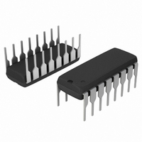
MC33368PG ON Semiconductor, MC33368PG Datasheet

MC33368PG
Specifications of MC33368PG
Related parts for MC33368PG
MC33368PG Summary of contents
Page 1
... Restart Delay Timer This is a Pb- -Free Device* *For additional information on our Pb--Free strategy and soldering details, please download the ON Semiconductor Soldering and Mounting Techniques Reference Manual, SOLDERRM/D. Semiconductor Components Industries, LLC, 2010 December, 2010 - - Rev. 10 supply voltage and a CMOS ...
Page 2
Restart Delay Restart Delay Output Overvoltage FB Multiplier/ Error Comp Amplifier Mult LEB Current Sense Current Sense WatchdogTimer/ ZC Det Zero Current Detector MAXIMUM RATINGS (T = 25C, unless otherwise noted) A Power Supply Voltage (Transient) Power Supply Voltage (Operating) ...
Page 3
ELECTRICAL CHARACTERISTICS (V Characteristic ERROR AMPLIFIER Input Bias Current ( Input Offset Voltage (V = 3.0 V) Comp Transconductance (V = 3.0 V) Comp Output Source ( Comp ...
Page 4
... Static Operating Current ( Line Pin Leakage (V = 500 V) Line ORDERING INFORMATION Device MC33368PG MC33368DG MC33368DR2G †For information on tape and reel specifications, including part orientation and tape sizes, please refer to our Tape and Reel Packaging Specifications Brochure, BRD8011/D. = 14.5 V, for typical values T CC Symbol = ...
Page 5
4.0 V Pin 25C 1 3.75 V 1.2 = 3.5 V 1.0 = 3.25 V 0.8 0.6 0.4 0.2 0 --0.2 0.6 1 MULTIPLIER PIN ...
Page 6
1.76 1.72 1.68 1.64 --55 -- AMBIENT TEMPERATURE (C) A Figure 8. Quickstart Charge Current versus Temperature 5.0 0 --5.0 5.0 ms/DIV Figure 10. Drive Output ...
Page 7
INTRODUCTION With the goal of exceeding the requirements of legislation on line current harmonic content, there is an ever increasing demand for an economical method of obtaining a unity power factor. This data sheet describes a monolithic control IC that ...
Page 8
Multiplier A single quadrant, two input multiplier is the critical element that enables this device to control power factor. The ac haversines are monitored at Pin 5 with respect to ground while the Error Amplifier output at Pin 4 is ...
Page 9
In this manner, the SMPS switching transistors are operated at very low duty cycles, preventing their destruction. If the short circuit fault is removed, the power supply system will turn on by itself in a normal startup mode after the ...
Page 10
Table 1. Design Equations Calculation Converter Output Power Peak Indicator Current Inductance Switch On--Time Switch Off--Time t (off) Minimum Switch Off--Time Delay Time t = – R10 Switching Frequency Peak Switch Current Multiplier Input ...
Page 11
EMI D1 D3 270 Filter Vrms V MC33368 ref V ref 330 mF AGND 8 1.5 V Set Dominant Overvoltage Comparator R5 1.3 M Low 1. ...
Page 12
D2 D4 EMI Filter 270 Vrms V ref V ref R8 1 2.2 AGND 8 1 1.3 M Low Load Detect Quickstart Mult 5 Multiplier C2 R3 0.01 10 ...
Page 13
Step--up Isolation Transformer Autoformer Line 115 Vrms Input Neutral An RFI filter is required for best performance when connecting the preconverter directly to the ac line. The filter attenuates the level of high frequency switching that appears on the ...
Page 14
EMI D1 D3 270 Filter Vac V ref V ref R8 1 AGND 330 1.3 M Low Load Detect Quickstart Mult 5 Multiplier C2 R3 0.01 ...
Page 15
DC Output IC1 R13 R10 J R11 Jumper 3.0 Figure 21. Printed Circuit Board and Component Layout (Circuits of Figures ...
Page 16
... Opportunity/Affirmative Action Employer. This literature is subject to all applicable copyright laws and is not for resale in any manner. PUBLICATION ORDERING INFORMATION LITERATURE FULFILLMENT: Literature Distribution Center for ON Semiconductor P.O. Box 5163, Denver, Colorado 80217 USA Phone: 303--675--2175 or 800--344--3860 Toll Free USA/Canada Fax: 303--675--2176 or 800--344--3867 Toll Free USA/Canada Email: orderlit@onsemi ...


