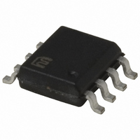
MIC2025-1YM Micrel Inc, MIC2025-1YM Datasheet - Page 11

MIC2025-1YM
Manufacturer Part Number
MIC2025-1YM
Description
IC SW DISTRIBUTION 1CHAN 8SOIC
Manufacturer
Micrel Inc
Series
MM8™r
Type
High Side Switchr
Datasheet
1.MIC2075-2YM.pdf
(14 pages)
Specifications of MIC2025-1YM
Current Limit
700mA
Number Of Outputs
1
Rds (on)
140 mOhm
Internal Switch(s)
Yes
Voltage - Input
2.7 ~ 5.5 V
Operating Temperature
-40°C ~ 85°C
Mounting Type
Surface Mount
Package / Case
8-SOIC (3.9mm Width)
Power Load Switch Type
High Side
Input Voltage
5.5V
On State Resistance
0.09ohm
Thermal Protection
Yes
On / Enable Input Polarity
Active High
No. Of Outputs
1
Short Circuit Current Limit
700mA
Input Voltage Range
2.7 to 5.5V
Number Of Switches
Single
Operating Temp Range
-40C to 85C
Operating Temperature Classification
Industrial
Mounting
Surface Mount
Pin Count
8
Package Type
SOP
Lead Free Status / RoHS Status
Lead free / RoHS Compliant
Other names
576-1057
Available stocks
Company
Part Number
Manufacturer
Quantity
Price
Company:
Part Number:
MIC2025-1YM
Manufacturer:
MICREL
Quantity:
1 325
Company:
Part Number:
MIC2025-1YM
Manufacturer:
MICREL
Quantity:
5 000
Company:
Part Number:
MIC2025-1YM
Manufacturer:
MIC
Quantity:
82
Part Number:
MIC2025-1YM
Manufacturer:
MICREL/麦瑞
Quantity:
20 000
Company:
Part Number:
MIC2025-1YM TR
Manufacturer:
MAXIM
Quantity:
6
Part Number:
MIC2025-1YM-TR
Manufacturer:
MICROCHIP/微芯
Quantity:
20 000
Company:
Part Number:
MIC2025-1YMM
Manufacturer:
MICREL
Quantity:
863
Part Number:
MIC2025-1YMM
Manufacturer:
MICREL/麦瑞
Quantity:
20 000
Part Number:
MIC2025-1YMM-TR
Manufacturer:
MICROCHIP/微芯
Quantity:
20 000
Part Number:
MIC2025-1YMTR
Manufacturer:
MICREL/麦瑞
Quantity:
20 000
Applications Information
Supply Filtering
A 0.1µF to 1µF bypass capacitor positioned close to V
GND of the device is strongly recommended to control sup-
ply transients. Without a bypass capacitor, an output short
may cause sufficient ringing on the input (from supply lead
inductance) to damage internal control circuitry.
Printed Circuit Board Hot-Plug
The MIC2025/75 are ideal inrush current-limiters suitable for
hot-plug applications. Due to the integrated charge pump,
the MIC2025/75 presents a high impedance when off and
slowly becomes a low impedance as it turns on. This “soft-
start” feature effectively isolates power supplies from highly
capacitive loads by reducing inrush current during hot-plug
events. Figure 3 shows how the MIC2075 may be used in a
hot-plug application.
In cases of extremely large capacitive loads (>400µF), the
length of the transient due to inrush current may exceed the
delay provided by the integrated filter. Since this inrush cur-
rent exceeds the current-limit delay specification, FLG will
be asserted during this time. To prevent the logic controller
from responding to FLG being asserted, an external RC filter,
as shown in Figure 4, can be used to filter out transient FLG
assertion. The value of the RC time constant will be selected
to match the length of the transient.
June 2010
to "Hot"
Receptacle
GND
V
C C
Logic Controller
OVERCURRENT
Figure 3. Hot Plug Application
Figure 4. Transient Filter
IN
and
0.1
µF
C
11
1
2
3
4
10k
R
Adaptor Card
E N
F L G
GND
NC
Universal Serial Bus (USB) Power Distribution
The MIC2025/75 is ideally suited for USB (Universal Serial
Bus) power distribution applications. The USB specification
defines power distribution for USB host systems such as
PCs and USB hubs. Hubs can either be self-powered or
bus-powered (that is, powered from the bus). Figure 5 below
shows a typical USB Host application that may be suited for
mobile PC applications employing USB. The requirements
for USB host systems is that the port must supply a minimum
of 500mA at an output voltage of 5V ±5%. In addition, the
output power delivered must be limited to below 25VA. Upon
an overcurrent condition, the host must also be notified. To
support hot-plug events, the hub must have a minimum of
120µF of bulk capacitance, preferably low-ESR electrolytic
or tantulum. Refer to Application Note 17 for more details on
designing compliant USB hub and host systems.
For bus-powered hubs, USB requires that each downstream
port be switched on or off under control by the host. Up to four
downstream ports each capable of supplying 100mA at 4.4V
minimum are allowed. In addition, to reduce voltage droop on
the upstream V
can consume up to 500mA from the upstream bus the hub
must consume only 100mA max at start-up, until it enumer-
ates with the host prior to requesting more power. The same
requirements apply for bus-powered peripherals that have no
downstream ports. Figure 6 shows a bus-powered hub.
MIC2025-2
V+
1
2
3
4
EN
FLG
GND
NC
OUT
OUT
NC
MIC2025
IN
8
7
6
5
OUT
OUT
NC
IN
BUS
C
8
7
6
5
BULK
, soft-start is necessary. Although the hub
Backend
Function
MIC2025/2075


