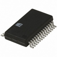
MIC2563A-1YSM Micrel Inc, MIC2563A-1YSM Datasheet

MIC2563A-1YSM
Specifications of MIC2563A-1YSM
Available stocks
Related parts for MIC2563A-1YSM
MIC2563A-1YSM Summary of contents
Page 1
... The MIC2563A switches between the three voltages (0V, 3.3V and 5.0V) and the V CC 0V, 3.3V 12.0V) required by PC Cards. The MIC2563A switches voltages from the system power supply Output voltage is selected by two digital inputs each and PP output current ranges for V The MIC2563A provides power management capability con- trolled by the PC Card logic controller ...
Page 2
... Ordering Information Part Number MIC2563A-0BSM MIC2563A-1BSM MIC2563A-0YSM MIC2563A-1YSM Note: See “MIC2563A-0 and MIC2563A-1 Control Logic Table“ for a description of the differences between the logic options. Pin Configuration Connect all pins with the same name together for proper operation. MIC2563A-1 Redefined Pin Assignment Some pin names for the MIC2563A-1 are different from the MIC2563A-0 ...
Page 3
... MIC2563A Absolute Maximum Ratings Supply Voltage ............................................... +15V ................................................................... +7.5V CC3 V IN ................................................................... +7.5V CC5 Logic Input Voltages ..................................... –0.3V to +10V Output Current (each output) V OUT ............................... >200mA, Internally Limited PP V OUT ..................................... >1A, Internally Limited CC Power Dissipation ( .......... Internally Limited D A SSOP .................................................................. 800mW Derating Factors (to Ambient) SSOP ................................................................. 4mW/ C Lead Temperature (5 sec ...
Page 4
... IN for operation. For single 5V supply systems, connect 5V to both V CC3 section for further details not required for operation must be either high impedance or greater than or approximately equal to the highest voltage V PP and 5V are connected to the MIC2563A, V M9999-110503 Condition ( OUT = 3. OUT = 5V to Hi-Z ...
Page 5
... PP is again disabled 100 for all measurements. Load capacitance is negligible Enable 3. 3. Output 0 V Enable is shown generically: refer to “MIC2563A-0 and MIC2563A-1 Control Logic Tables” for specific control logic input time “A,” programmed to 3.3V. At “B,” March 2004 12V OFF t 9 ...
Page 6
... MIC2563A MIC2563A-0 Control Logic Table V V CC5_EN CC3_EN MIC2563A-1 Control Logic Table V V CC5_EN CC3_EN M9999-110503 EN1 EN0 0 0 Clamped to Ground 0 1 Clamped to Ground 1 0 Clamped to Ground 1 1 Clamped to Ground (compatible with Cirrus Logic CL-PD6710 & PD672x-series Controllers PP_PGM PP_VCC 0 0 Clamped to Ground ...
Page 7
... MIC2563A Logic Block Diagram A EN1 A EN0 A V CC5_EN A V CC3_EN A V CC3 CC5 IN B EN1 B EN0 B V CC5_EN B V CC3_EN V CC3 IN V CC5 IN March 2004 MIC2563 Section A Control Logic I LIMIT / Thermal Shutdown Gate Drive Generator MIC2563 Section B Control Logic I LIMIT / Thermal ...
Page 8
... IN, and V IN inputs PP During flash memory programming with standard (+12V) flash memories, the PC Card slot logic controller outputs a ( the EN0, EN1 control pins of the MIC2563A, which connects V resistance of the MIC2563A switch allows using a small OUT pins may use PP bypass capacitor on the V action performed by a large filter capacitor on V the main power supply filter capacitor is sufficient) ...
Page 9
... MIC2563A Figure 3. PC Card Slot Power Control Application with Dual V Figure 4. Typical PC Card Slot Power Control Application March 2004 5V (opt) System Power 3.3V Supply 12V (opt) V CC3 CC5 IN (opt) EN0 EN1 V CC5_EN V CC3_EN MIC2563 PCMCIA Card Slot Controller EN0 EN1 V CC5_EN ...
Page 10
... MIC2563A Figure 5. PC Card Slot Power Control Application Note and V IN lines are driven together. The MIC2563A is powered from the V CC3 CC5 V OUT will be 5V when either V CC CC3 RST SER_DATA 74x574 SER_CLK 11 SER_LATCH Figure 6. Interfacing the MIC2563A with a Serial-Output Data Controller Pinouts shown are for the MIC2563A-1 and a three-wire serial controller ...
Page 11
... Quad Flip-Flop with Latches (two needed) Either 3. logic devices may be used, depending upon the control voltage employed by the slot logic controller. Pin numbers in parenthesis refer to the MIC2563A-1BSM. Gerber files for this PC board layout are available to Micrel custom- ers. Please contact Micrel directly. ...
Page 12
... MIC2563A Package Information 0.875 (0.034) REF 10.33 (0.407) 10.07 (0.396) 0.38 (0.015) 0.25 (0.010) 0.65 (0.0260) BSC MICREL, INC. 1849 FORTUNE DRIVE SAN JOSE, CA 95131 USA + 1 (408) 944-0800 TEL The information furnished by Micrel in this data sheet is believed to be accurate and reliable. However, no responsibility is assumed by Micrel for its use. ...


