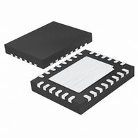
LTC3557EUF-1#PBF Linear Technology, LTC3557EUF-1#PBF Datasheet - Page 13

LTC3557EUF-1#PBF
Manufacturer Part Number
LTC3557EUF-1#PBF
Description
IC USB POWER MANAGE 28-QFN
Manufacturer
Linear Technology
Datasheet
1.LTC3557EUFPBF.pdf
(28 pages)
Specifications of LTC3557EUF-1#PBF
Applications
Handheld/Mobile Devices
Voltage - Supply
4.35 V ~ 5.5 V
Operating Temperature
-40°C ~ 85°C
Mounting Type
Surface Mount
Package / Case
28-QFN
Lead Free Status / RoHS Status
Lead free / RoHS Compliant
Current - Supply
-
Available stocks
Company
Part Number
Manufacturer
Quantity
Price
The LTC3557/LTC3557-1 includes three 2.25MHz constant
frequency current mode step-down switching regulators
providing 400mA, 400mA and 600mA each. All step-
down switching regulators can be programmed for a
minimum output voltage of 0.8V and can be used to power
a microcontroller core, microcontroller I/O, memory or
other logic circuitry. All step-down switching regulators
support 100% duty cycle operation and are capable of
operating in Burst Mode operation for highest effi ciencies
at light loads (Burst Mode operation is pin selectable). No
external compensation components are required for the
switching regulators.
USB PowerPath Controller
The input current limit and charge control circuits of the
LTC3557/LTC3557-1 are designed to limit input current
as well as control battery charge current as a function of
I
the three step-down switching regulators, always on 3.3V
LDO and the battery charger.
If the combined load does not exceed the programmed
input current limit, V
an internal 200mΩ P-channel MOSFET.
If the combined load at V
input current limit, the battery charger will reduce its charge
current by the amount necessary to enable the external
load to be satisfi ed while maintaining the programmed
input current. Even if the battery charge current is set to
exceed the allowable USB current, the average input current
USB specifi cation will not be violated. Furthermore, load
current at V
available current will be used to charge the battery.
The current out of the CLPROG pin is a fraction (1/h
of the V
nected from CLPROG to GND, the voltage on CLPROG
represents the input current:
where I
Characteristics.
OPERATION
VOUT
I
VBUS
. V
BUS
OUT
BUSQ
= I
current. When a programming resistor is con-
OUT
BUSQ
drives the combination of the external load,
and h
will always be prioritized and only excess
+
R
V
OUT
CLPROG
CLPROG
CLPROG
will be connected to V
OUT
are given in the Electrical
• h
exceeds the programmed
CLPROG
BUS
through
CLPROG
)
The input current limit is programmed by the ILIM0 and
ILIM1 pins. The LTC3557/LTC3557-1 can be confi gured to
limit input current to one of several possible settings as well
as be deactivated (USB Suspend). The input current limit
will be set by the appropriate servo voltage and the resistor
on CLPROG according to the following expression:
Under worst-case conditions, the USB specifi cation will not
be violated with an R
Table 1 shows the available settings for the ILIM0 and
ILIM1 pins:
Table 1: Controlled Input Current Limit
Notice that when ILIM0 is high and ILIM1 is low, the input
current limit is set to a higher current limit for increased
charging and current availability at V
typically used when there is power available from a wall
adapter.
Ideal Diode from BAT to V
The LTC3557/LTC3557-1 has an internal ideal diode as well
as a controller for an optional external ideal diode. Both
the internal and the external ideal diodes respond quickly
whenever V
If the load increases beyond the input current limit, ad-
ditional current will be pulled from the battery via the
ideal diodes. Furthermore, if power to V
V
removed, then all of the application power will be provided
OUT
I
I
I
VBUS
VBUS
VBUS
(external wall power or high voltage regulator) is
ILIM1
0
0
1
1
= I
= I
= I
OUT
BUSQ
BUSQ
BUSQ
drops below BAT.
LTC3557/LTC3557-1
+
+
+
R
R
R
CLPROG
CLPROG
CLPROG
CLPROG
0.2V
2V
1V
ILIM0
OUT
0
1
0
1
resistor of greater than 2.1k.
• h
• h
• h
CLPROG
CLPROG
CLPROG
OUT
(
(
(
1x Mode
5x Mode
10x Mode
. This mode is
100mA (1x)
500mA (5x)
BUS
I
1A (10x)
Suspend
BUS(LIM)
(USB) or
13
)
)
)
35571fc


