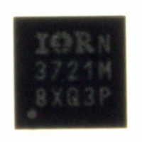
IR3721MTRPBF International Rectifier, IR3721MTRPBF Datasheet - Page 11

IR3721MTRPBF
Manufacturer Part Number
IR3721MTRPBF
Description
IC POWER SUPPLY MONITOR 10-DFN
Manufacturer
International Rectifier
Series
TruePower™r
Datasheet
1.IR3721MTRPBF.pdf
(16 pages)
Specifications of IR3721MTRPBF
Applications
Power Supply Monitor
Voltage - Supply
3.135 V ~ 3.465 V
Current - Supply
350µA
Operating Temperature
0°C ~ 125°C
Mounting Type
Surface Mount
Package / Case
10-DFN
Quiescent Current
450µA
Bandwidth
589kHz
Sensor Case Style
DFN
No. Of Pins
10
Supply Voltage Range
3.135V To 3.465V
Operating Temperature Range
0°C To +125°C
Filter Terminals
SMD
Rohs Compliant
No
Accuracy %
2.5%
Package
10 Lead 3x3 DFN
Static Accuracy
2.5% @ 65oC
Vk Range
0.5V - 1.8V
Vcs Range
5mV - 150mV
Bias Supply Voltage
+3.3V +/-5%
Junction Temperature
0oC to 125oC
Pbf
Yes
Lead Free Status / RoHS Status
Lead free / RoHS Compliant
Voltage - Input
-
Other names
IR3721MTRPBFTR
Available stocks
Company
Part Number
Manufacturer
Quantity
Price
Part Number:
IR3721MTRPBF
Manufacturer:
IR
Quantity:
20 000
LAYOUT GUIDELINES
Refer to figures 7 through 11 for guidance laying out
the IR3721. These guidelines also apply to resistive
current sensing. The following guidelines will
minimize sources of noise and error, which is
required because millivolt level signals correspond to
amps of inductor current.
1. Place the capacitor Ccs2 close to the VO and
2. Sense the inductor (or shunt) Kelvin style at its
3. Route signal VOUT back to the IC VK pin on its
4. Place the thermistor near the inductor. Refer to
Figure 7 Example schematic
Page 11 of 16
VCS pins of the IR3721. Treat VO and VCS as a
differential signal pair back to the IC as shown in
the elliptical area designated #1 of figure 8.
terminals. Route the leads back as a differential
pair. Refer to area #2 of figure 8.
own dedicated trace. Refer to area #3 of figure 8.
area #4 of figure 8. Route the thermistor leads
back to the rest of the network using differential
traces. Mount the rest of the thermistor network
consisting of Rs, Rp, and R1 close to the IC.
Rcs1
1
L1
Rcs2
2
Ccs1
0
Ccs2
Rs
Rp
www.irf.com
1
2
3
4
5
CS
VO
RT
GND_1
VCC
U1
IR3721
Rth
R1
GND_3
GND_4
VCC_1
VK
DI
10
9
8
7
6
5. Use an isolated dedicated ground plane
6. Bypass IC VDD pin 5 to GND pin 4 with a high
7. Bypass the IC VK pin to GND with a high quality
connected only to components associated with
the IR3721 that connect to GND as shown in
figure 9. Connect this dedicated ground plane at
one location only to the ground of the monitored
voltage. The thermally relived via in figure eight
illustrates this connection.
quality 0.1 μF ceramic capacitor. Refer to area #6
of figure 8.
0.1 μF ceramic capacitor. Refer to area #7 of
figure 8.
C_VDD
0.1uF
C_VK
0.1uF
R_DI_FILT
C_DI_FILT
VOUT
VOUT
DI_FILT
VDD
GND
DATA SHEET
IR3721
09/15/08


