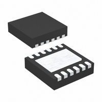
LTC2953IDD-2#TRPBF Linear Technology, LTC2953IDD-2#TRPBF Datasheet

LTC2953IDD-2#TRPBF
Specifications of LTC2953IDD-2#TRPBF
Available stocks
Related parts for LTC2953IDD-2#TRPBF
LTC2953IDD-2#TRPBF Summary of contents
Page 1
... The LTC2953 operates over a wide 2.7V to 27V input voltage range and draws only 14μA of current. Two ver- sions of the part accommodate either positive or negative enable polarities. , LT, LTC and LTM are registered trademarks of Linear Technology Corporation. All other trademarks are the property of their respective owners ...
Page 2
... LTC2953IDD-1#PBF LTC2953IDD-1#TRPBF LTC2953IDD-2#PBF LTC2953IDD-2#TRPBF Consult LTC Marketing for parts specifi ed with wider operating temperature ranges. *The temperature grade is identifi label on the shipping container. Consult LTC Marketing for information on non-standard lead based fi nish parts. For more information on lead free part marking, go to: For more information on tape and reel specifi ...
Page 3
ELECTRICAL CHARACTERISTICS temperature range, otherwise specifi cations are at T SYMBOL PARAMETER EN/ ⎯ E ⎯ N Leakage Current I EN(LKG) EN/ ⎯ E ⎯ N Voltage Output Low V EN(VOL) EN/ ⎯ E ⎯ N Lock Out Time (Note ...
Page 4
LTC2953 ELECTRICAL CHARACTERISTICS temperature range, otherwise specifi cations are at T SYMBOL PARAMETER ⎯ P ⎯ F ⎯ I Leakage Current I PFI(LKG) ⎯ P ⎯ Leakage Current I PFO(LKG) I UVLO Leakage Current UVLO(LKG Input ...
Page 5
TYPICAL PERFORMANCE CHARACTERISTICS Supply Current vs Temperature 27V 3. 2. –50 – TEMPERATURE (°C) 2953 G01 Turn Off Interrupt Debounce Time (t ) ...
Page 6
LTC2953 TYPICAL PERFORMANCE CHARACTERISTICS EN (LTC2953-1) Voltage 1 25°C A 100k PULL-UP FROM 0.8 0.6 0.4 0 (V) IN '#! / ⎯ R ⎯ S ...
Page 7
PIN FUNCTIONS GND (Pin 1): Ground. VM (Pin 2): Voltage Monitor Input. Input to an accurate comparator with a 0.5V threshold. VM controls the state of the ⎯ R ⎯ S ⎯ T output pin and is independent of ⎯ ...
Page 8
LTC2953 BLOCK DIAGRAM V IN 2.7V TO 27V 1.5k 34V ZENER + 0.5V VM – RST 2.4V 100k PB HV 0.8V UVLO HV – + 0.5V 8 REGULATOR 2.4V 200 ms RST DELAY DEBOUNCE AND 10μs FILTER LOGIC DEBOUNCE AND ...
Page 9
TIMING DIAGRAMS PB EN (LTC2953-1) KILL PB PDT INT UVLO EN (LTC2953-1) Figure 2. ⎯ P ⎯ B Interrupt Pulse: ⎯ P ⎯ B Low for t PB, UVLO AND KILL IGNORED t t DB, ON KILL, ON BLANK DO ...
Page 10
LTC2953 TIMING DIAGRAMS UVLO PDT INT PB EN (LTC2953-1) Figure 3. UVLO Interrupt Pulse: UVLO Low for t PB PDT INT EN (LTC2953-1) UVLO Figure 4. Push Button Power Down Timing: ⎯ P ⎯ B Pressed and Held Low for ...
Page 11
TIMING DIAGRAMS UVLO PDT INT EN (LTC2953-1) PB Figure 5. UVLO Power Down Timing: UVLO Low for t > (t 0.5V 0. RST RST Figure 6. Voltage Monitor Reset Timing (LTC2953-1) Figure 8. ⎯ K ⎯ ...
Page 12
LTC2953 OPERATION The LTC2953 is a push button On/Off controller with dual function input and output supply monitors. The part con- tains all the circuitry needed to debounce a push button input and provides a simple μP handshake protocol for ...
Page 13
APPLICATIONS INFORMATION PUSH BUTTON CONTROL Power On Sequence To enable system power, the push button input ( ⎯ P ⎯ must be held low continuously for 32ms (t enable output (EN/ ⎯ E ⎯ asserted, ...
Page 14
LTC2953 APPLICATIONS INFORMATION PB, UVLO AND KILL TURN ON ABORTED (LTC2953-1) KILL SYSTEM FAILS TO SET KILL HIGH Figure 12. Aborted Power On Sequence, ⎯ K ⎯ I ⎯ L ⎯ L Remaining Low Aborts ...
Page 15
APPLICATIONS INFORMATION + 8.4V LTC2953-1 UVLO R14 COMPARATOR 2150k UVLO – 5.4V TH 50mV + 0.5V R13 23.2k PFI – 6.04V TH 4mV R12 196k + 0.5V POWER FAIL COMPARATOR Figure 14. Dual Function Battery Comparators ...
Page 16
LTC2953 TYPICAL APPLICATIONS Push Button Buffer The circuit of Figure 16 shows the power fail comparator sensing the push button input. The ⎯ P ⎯ F ⎯ O output toggles each time the push button crosses 0.5V. This application provides ...
Page 17
TYPICAL APPLICATIONS Push Button Controlled μP Reset The circuit of Figure 19 can be used to keep a μP in reset for 200ms after the push button has enabled system power. After system power has stabilized, the voltage monitor input ...
Page 18
LTC2953 TYPICAL APPLICATIONS Dual Supply Monitor with μP Reset The circuit of Figure 22 monitors two supplies and provides a μP reset. When either the ⎯ P ⎯ F ⎯ the VM input voltage falls below its threshold ...
Page 19
... SHADED AREA IS ONLY A REFERENCE FOR PIN 1 LOCATION ON THE TOP AND BOTTOM OF PACKAGE Information furnished by Linear Technology Corporation is believed to be accurate and reliable. However, no responsibility is assumed for its use. Linear Technology Corporation makes no representa- tion that the interconnection of its circuits as described herein will not infringe on existing patent rights. DD Package 12-Lead Plastic DFN (3mm × ...
Page 20
... Automatic Switchover, Charges 1-Cell Li-Ion Batteries No External MOSFET, Automatic Switching Between DC Sources Effi cient Diode-ORing, Automatic Switching Between DC Sources 36V ● www.linear.com V IN OUT DC/DC 3.3V R1 100k RST PFO SYSTEM INT LOGIC KILL 2953 F25 LT 0607 • PRINTED IN USA © LINEAR TECHNOLOGY CORPORATION 2007 2953f ...


