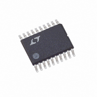
LTC2922IF-3.3 Linear Technology, LTC2922IF-3.3 Datasheet - Page 9

LTC2922IF-3.3
Manufacturer Part Number
LTC2922IF-3.3
Description
IC 5 PWR SUPPLY MONITOR 20TSSOP
Manufacturer
Linear Technology
Datasheet
1.LTC2921CGN-3.3.pdf
(20 pages)
Specifications of LTC2922IF-3.3
Applications
Five Power Supply Monitor
Voltage - Supply
2.97 V ~ 3.63 V
Current - Supply
2mA
Operating Temperature
-40°C ~ 85°C
Mounting Type
Surface Mount
Package / Case
20-TSSOP
Lead Free Status / RoHS Status
Contains lead / RoHS non-compliant
Voltage - Input
-
Available stocks
Company
Part Number
Manufacturer
Quantity
Price
Company:
Part Number:
LTC2922IF-3.3#PBF
Manufacturer:
PHILIPS
Quantity:
899
Company:
Part Number:
LTC2922IF-3.3PBF
Manufacturer:
SIEMENS
Quantity:
48
OPERATIO
Electronic Circuit Breaker
Placing a resistor between the V
the part to detect shorts and excessive currents on the V
supply. The electronic circuit breaker trips when the
voltage across the resistor is >50mV for more than 1 s. A
trip causes a fault condition which interrupts the monitor
TI I G DIAGRA S
The timing of a typical start-up sequence for the LTC2921/
LTC2922 is shown in Figure 2. V
lockout level at time 0. All monitor inputs settle between
the 0.5V monitor threshold and the 0.7V overvoltage
threshold by time 1, then a TIMER cycle starts. The TIMER
pin reaches 1.2V at time 2, and GATE ramping begins.
When the GATE ramp completes at time 3, the automatic
remote sense switches close. Another TIMER delay
begins at time 4 and finishes at time 5, at which time PG
is activated.
W U
REMOTE
SWITCH
SENSE
TIMER
SENSE
GATE
GATE
V
PG
V1
V2
V3
V4
CC
Figure 2. Typical Start-Up Sequence
0
0.7V
0.5V
0.7V
0.5V
UNDERVOLTAGE
LOCKOUT LEVEL
0.7V
0.5V
U
0.7V
0.5V
1
1.2V
2
W
V
CC
CC
V
V
CC
CC
CC
exceeds the undervoltage
-50mV
and SENSE pins allows
3
4
1.2V
5
CC
sequence, and which requires reset of the circuit breaker
latch (see Interrupting Events section). Breaker reset is
achieved by pulling V1 below the reset threshold for
>150 s after the current falls below the trip point, or by
returning from undervoltage lockout on V
The timing of a monitor failure and subsequent regular
turn-on is shown in Figure 3. Prior to time 1, a successful
turn-on sequence had completed. At time 1, monitor V2
falls below the 0.5V reference, triggering an error. The
GATE pin, PG pin, and the remote sense switches fall at
rates determined by the pull-down currents and loading
conditions of each (times 2, 3, 4). At time 5, monitor V2
recovers, and a normal turn-on sequence begins.
REMOTE
SWITCH
SENSE
TIMER
Figure 3. Monitor Failure and Start-Up Sequence Timing
SENSE
GATE
GATE
V
PG
V1
V2
V3
V4
CC
LTC2921/LTC2922 Series
1
0.7V
0.5V
UNDERVOLTAGE
LOCKOUT LEVEL
2 3 4
0.7V
0.5V
0.7V
0.5V
5
0.7V
0.5V
0.7V
0.5V
V
CC
1.2V
V
V
CC
CC
CC
-50mV
.
1.2V
29212fa
9


