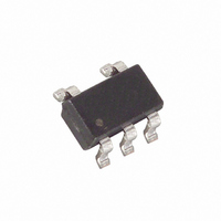
MAX6518UKP045+T Maxim Integrated Products, MAX6518UKP045+T Datasheet - Page 7

MAX6518UKP045+T
Manufacturer Part Number
MAX6518UKP045+T
Description
IC TEMP SENSOR SW SOT23-5
Manufacturer
Maxim Integrated Products
Datasheet
1.MAX6518UKP095T.pdf
(10 pages)
Specifications of MAX6518UKP045+T
Function
Temp Switch
Topology
Comparator, Voltage Reference
Sensor Type
Internal
Sensing Temperature
45°C Trip Point
Output Type
Active High/Push-Pull
Output Alarm
Yes
Output Fan
Yes
Voltage - Supply
2.7 V ~ 5.5 V
Operating Temperature
-55°C ~ 125°C
Mounting Type
Surface Mount
Package / Case
SOT-23-5, SC-74A, SOT-25
Temperature Threshold
+ 45 C
Full Temp Accuracy
+/- 3 C
Gain
- 10.62 mV / C
Maximum Operating Temperature
+ 125 C
Minimum Operating Temperature
- 55 C
Lead Free Status / RoHS Status
Lead free / RoHS Compliant
• Calculate the temperature using the formula:
• Verify that the temperature measured is within ±2°C
• Connect OUT to ground (OUT to V
• Disconnect OUT from ground and observe that the
The MAX6516–MAX6519 can be programmed with 2°C
or 10°C of hysteresis by pin strapping HYST to V
GND, respectively. Below is a test feature that can be
used to measure the accuracy of the device’s hystere-
sis using a device with a +65°C threshold:
• Power up the device and observe the state of the
• Drive the OUT voltage down gradually.
• When the digital output changes state, note V
• V
• Calculate trip temperature (T1) using:
• Gradually raise V
• Calculate trip temperature (T2).
• T
of the ambient board temperature. Measure the
ambient board temperature using an accurate cali-
brated temperature sensor.
threshold versions) and observe the state change of
the logic output.
logic output reverts to its initial state.
digital output.
(high to low or low to high).
its initial state and note V
HYST
OUT
trip = V
Low-Cost, 2.7V to 5.5V, Analog Temperature
= T2 - T1.
T
T
OUT
=
=
_______________________________________________________________________________________
OUT
1 8015
1 8015
.
.
at logic output change of state
0 01062
0 01062
.
until the digital output reverts to
.
−
−
OUT
V
V
OUT
OUT
Hysteresis Testing
.
+
+
30
30
CC
for cold
Sensor Switches in a SOT23
OUT
CC
.
or
The MAX6516–MAX6519 supply current is typically 22µA.
When used to drive high-impedance loads, the devices
dissipate negligible power. Therefore, the die tempera-
ture is essentially the same as the package temperature.
Accurate temperature monitoring depends on the thermal
resistance between the device being monitored and the
MAX6516–MAX6519 die. Heat flows in and out of plastic
packages, primarily through the leads. Pin 2 of the 5-pin
SOT23 package provides the lowest thermal resistance to
the die. Short, wide copper traces between the
MAX6516–MAX6519 and the object whose temperature
is being monitored ensures heat transfers occur quickly
and reliably. The rise in die temperature due to self-heat-
ing is given by the following formula:
where P
MAX6516–MAX6519, and θ
of the package.
The typical thermal resistance is 140°C/W for the
5-pin SOT23 package. To limit the effects of self-
heating, minimize the output current. For example, if the
MAX6516–MAX6519 sink 1mA, the open-drain output
voltage is guaranteed to be less than 0.3V. Therefore,
an additional 0.3mW of power is dissipated within the
IC. This corresponds to a 0.042°C shift in the die tem-
perature in the 5-pin SOT23 package.
PROCESS: BiCMOS
DISSIPATION
ΔT
J
= P
is the power dissipated by the
DISSIPATION
Thermal Considerations
JA
Chip Information
is the thermal resistance
✕
θ
JA
7


