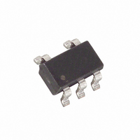
DS1775R7+T&R Maxim Integrated Products, DS1775R7+T&R Datasheet - Page 13

DS1775R7+T&R
Manufacturer Part Number
DS1775R7+T&R
Description
IC THERMOM/STAT DIG 111 SOT-23-5
Manufacturer
Maxim Integrated Products
Datasheet
1.DS1775RTR.pdf
(14 pages)
Specifications of DS1775R7+T&R
Function
Thermometer, Thermostat
Topology
ADC, Comparator, Register Bank
Sensor Type
Internal
Sensing Temperature
-55°C ~ 125°C
Output Type
I²C™/SMBus™
Output Alarm
Yes
Output Fan
No
Voltage - Supply
2.7 V ~ 5.5 V
Operating Temperature
-55°C ~ 125°C
Mounting Type
Surface Mount
Package / Case
SOT-23-5, SC-74A, SOT-25
Full Temp Accuracy
+/- 3 C
Digital Output - Bus Interface
Serial (2-Wire)
Digital Output - Number Of Bits
12 bit
Maximum Operating Temperature
+ 125 C
Minimum Operating Temperature
- 55 C
Lead Free Status / RoHS Status
Lead free / RoHS Compliant
AC ELECTRICAL CHARACTERISTICS:
2–WIRE INTERFACE
PARAMETER
SCL clock frequency
Bus free time between a
STOP and START
condition
Hold time (repeated)
START condition
LOW period of SCL
HIGH period of SCL
Set-up time for a
repeated START
Data hold time
Data set-up time
Rise time of both SDA and
SCL signals
Fall time of both SDA and
SCL signals
Set-up time for STOP
Capacitive load for each bus
line
Input Capacitance
NOTES:
1. All voltages are referenced to ground.
2. I/O pins of fast mode devices must not obstruct the SDA and SCL lines if V
3. I
4. I
5. After this period, the first clock pulse is generated.
6. The maximum t
7. A fast mode device can be used in a standard mode system, but the requirement t
8. C
9. Internal heating caused by O.S. loading will cause the DS1775 to read approximately 0.5ºC higher if
10. Contact the factory in Dallas, (972) 371-4448, for operation requiring temperature readings greater
SCL signal.
then be met. This will automatically be the case if the device does not stretch the LOW period of the
SCL signal. If such a device does stretch the LOW period of the SCL signal, it must output the next
data bit to the SDA line t
O.S. is sinking the max rated current.
than 120°C.
DD
DD
b
– total capacitance of one bus line in pF.
specified with O.S. pin open.
specified with V
HD:DAT
DD
has only to be met if the device does not stretch the LOW period (t
at 5.0V and SDA, SCL = 5.0V, 0°C to +70°C.
R MAX
SYMBOL
t
t
t
t
t
HD:DAT
HD:STA
SU:DAT
SU:STA
SU:STO
t
t
t
f
+t
HIGH
LOW
BUF
C
SCL
C
t
t
R
F
SU:DAT
b
I
= 1000+250 = 1250 ns before the SCL line is released.
Standard Mode
Standard Mode
Standard Mode
Standard Mode
Standard Mode
Standard Mode
Standard Mode
Standard Mode
Standard Mode
Standard Mode
Standard Mode
CONDITION
Fast Mode
Fast Mode
Fast Mode
Fast Mode
Fast Mode
Fast Mode
Fast Mode
Fast Mode
Fast Mode
Fast Mode
Fast Mode
13 of 14
(–55°C to +125°C; V
0.1C
0.1C
MIN
100
250
20+
20+
1.3
4.7
0.6
4.0
1.3
4.7
0.6
4.0
0.6
4.7
0.6
4.0
0
0
B
B
TYP
5
MAX
1000
400
100
300
300
300
400
DD
0.9
0.9
is switched off.
DD
SU:DAT
=2.7V to 5.5V)
UNITS NOTES
KHZ
pF
pF
ms
ms
ms
ms
ms
ms
ms
ns
ns
ns
³ 250 ns must
LOW
) of the
5
6
7
8
8
8


