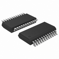
ADT7476AARQZ-RL7 ON Semiconductor, ADT7476AARQZ-RL7 Datasheet - Page 25

ADT7476AARQZ-RL7
Manufacturer Part Number
ADT7476AARQZ-RL7
Description
IC REMOTE THERMAL CTLR 24-QSOP
Manufacturer
ON Semiconductor
Series
dBCool®r
Datasheet
1.ADT7476AARQZ.pdf
(67 pages)
Specifications of ADT7476AARQZ-RL7
Function
Fan Control, Temp Monitor
Topology
ADC, Comparator, Fan Speed Counter, Multiplexer, Register Bank
Sensor Type
External & Internal
Sensing Temperature
-40°C ~ 125°C, External Sensor
Output Type
SMBus™
Output Alarm
No
Output Fan
Yes
Voltage - Supply
3 V ~ 3.6 V
Operating Temperature
-40°C ~ 125°C
Mounting Type
Surface Mount
Package / Case
24-QSOP
Full Temp Accuracy
+/- 0.5 C
Digital Output - Bus Interface
Serial (3-Wire, 4-Wire)
Maximum Operating Temperature
+ 125 C
Minimum Operating Temperature
- 40 C
Lead Free Status / RoHS Status
Lead free / RoHS Compliant
Configuring the Relevant THERM Behavior
1. Configure the desired pin as the THERM timer
2. Select the desired fan behavior for THERM timer
3. Select whether THERM timer events should
4. Select a suitable THERM limit value.
5. Select a THERM monitoring time.
Alternatively, OS- or BIOS-level software can
timestamp when the system is powered on. If an
SMBALERT is generated due to the THERM timer
limit being exceeded, another timestamp can be
taken. The difference in time can be calculated for a
fixed THERM timer limit time. For example, if it
takes one week for a THERM timer limit of 2.914 sec
to be exceeded, and the next time it takes only 1 hour,
input.
events.
generate SMBALERT interrupts.
Setting Bit 1 (THERM timer enable) of
Configuration Register 3 (0x78) enables the
THERM timer monitoring functionality. This is
disabled on Pin 14 and Pin 22 by default.
Setting Bit 0 and Bit 1 (PIN14FUNC) of
Configuration Register 4 (0x7D) enables THERM
timer output functionality on Pin 22 (Bit 1 of
Configuration Register 3, THERM, must also be
set). Pin 14 can also be used as TACH4.
Assuming the fans are running, setting Bit 2
(BOOST bit) of Configuration Register 3 (0x78)
causes all fans to run at 100% duty cycle whenever
THERM is asserted. This allows fail-safe system
cooling. If this bit is 0, the fans run at their current
settings and are not affected by THERM events. If
the fans are not already running when THERM
is asserted, then the fans do not run to full speed.
Setting Bit 5 (F4P) of Mask Register 2 (0x75) or Bit
0 of Mask Register 1 (0x74), depending on which
pins are configured as a THERM timer, masks
SMBALERTs when the THERM timer limit value
is exceeded. This bit should be cleared if
SMBALERTs based on THERM events are
required.
This value determines whether an SMBALERT is
generated on the first THERM assertion, or if only
a cumulative THERM assertion time limit is
exceeded. A value of 0x00 causes an SMBALERT
to be generated on the first THERM assertion.
This value specifies how often OS- or BIOS-level
software checks the THERM timer. For example,
BIOS can read the THERM timer once an hour to
determine the cumulative THERM assertion time.
If, for example, the total THERM assertion time is
<22.76 ms in Hour 1, >182.08 ms in Hour 2, and
>5.825 s in Hour 3, system performance is
degrading significantly because THERM is
asserting more frequently on an hourly basis.
http://onsemi.com
25
Configuring the THERM Pin as an Output
ADT7476A can optionally drive THERM low as an output.
When PROCHOT is bidirectional, THERM can be used to
throttle the processor by asserting PROCHOT. The user can
preprogram
temperature exceeds a thermal limit by 0.25°C, THERM
asserts low. If the temperature is still above the thermal limit
on the next monitoring cycle, THERM stays low. THERM
remains asserted low until the temperature is equal to or
below the thermal limit. Because the temperature for that
channel is measured only once for every monitoring cycle,
after THERM asserts, it is guaranteed to remain low for at
least one monitoring cycle.
Remote 1, local, or Remote 2 THERM temperature limits
are exceeded by 0.25°C. The THERM temperature limit
registers are at Register 0x6A, Register 0x6B, and Register
0x6C, respectively. Setting Bits [5:7] of Configuration
Register 5 (0x7C) enables the THERM output feature for the
Remote 1, local, and Remote 2 temperature channels,
respectively. Figure 34 shows how the THERM pin asserts
low as an output in the event of a critical overtemperature.
the THERM temperature limit to –63°C or less in Offset 64
mode, or −128°C or less in twos complement mode; that is,
for THERM temperature limit values less than –63°C or
–128°C, respectively, THERM is disabled.
Enabling and Disabling THERM on individual Channels
combinations of temperature channels using Bits [7:5] of
Configuration Register 5 (0x7C).
THERM Hysteresis
THERM hysteresis.
(Bit 2 of Configuration Register 4, 0x7D), the THERM pin
does not assert low when a THERM event occurs. If
Figure 34. Asserting THERM as an Output, Based on
In addition to monitoring THERM as an input, the
The THERM pin can be configured to assert low, if the
An alternative method of disabling THERM is to program
THERM can be enabled/disabled for individual or
Setting Bit 0 of Configuration Register 7 (0x11) disables
If THERM hysteresis is enabled and THERM is disabled
THERM LIMIT
THERM LIMIT
TEMP
THERM
0.25°C
then a serious degradation in system performance
has occurred.
system-critical
Tripping THERM Limits
MONITORING
CYCLE
thermal
limits.
If
the


