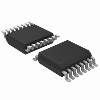
ADT7473ARQZ-RL7 ON Semiconductor, ADT7473ARQZ-RL7 Datasheet - Page 28

ADT7473ARQZ-RL7
Manufacturer Part Number
ADT7473ARQZ-RL7
Description
IC REMOTE THERMAL CTLR 16QSOP
Manufacturer
ON Semiconductor
Series
dBCool®r
Datasheet
1.ADT7473ARQZ-1RL.pdf
(74 pages)
Specifications of ADT7473ARQZ-RL7
Function
Fan Control, Temp Monitor
Topology
ADC, Comparator, Fan Speed Counter, Multiplexer, Register Bank
Sensor Type
External & Internal
Sensing Temperature
-40°C ~ 125°C, External Sensor
Output Type
SMBus™
Output Alarm
No
Output Fan
Yes
Voltage - Supply
3 V ~ 3.6 V
Operating Temperature
-40°C ~ 125°C
Mounting Type
Surface Mount
Package / Case
16-QSOP
Full Temp Accuracy
+/- 0.5 C
Digital Output - Bus Interface
Serial (3-Wire, 4-Wire)
Maximum Operating Temperature
+ 125 C
Minimum Operating Temperature
- 40 C
Lead Free Status / RoHS Status
Lead free / RoHS Compliant
connected directly to a dc source. For optimal results, the
associated dc bit should always be set when using 4−wire
fans.
Calculating Fan Speed
pulses per revolution being measured), fan speed is
calculated by:
reading.
Example
TACH1 High Byte (Register 0x29) = 0x17
TACH1 Low Byte (Register 0x28) = 0xFF
Fan Pulses per Revolution
four TACH pulses per revolution. Once the number of fan
TACH pulses has been determined, it can be programmed
into the fan pulses per revolution register (Register 0x7B)
for each fan. Alternatively, this register can be used to
determine the number or pulses per revolution output by a
given fan. By plotting fan speed measurements at a 100%
speed with different pulses per revolution setting, the
smoothest graph with the lowest ripple determines the
correct pulses per revolution value.
TACH Pulses per Revolution Register
Bits [1:0] Fan 1 default = 2 pulses per revolution
Bits [3:2] Fan 2 default = 2 pulses per revolution
Bits [5:4] Fan 3 default = 2 pulses per revolution
Bits [7:6] Fan 4 default = 2 pulses per revolution
Fan Spin−Up
function. It spins the fan at 100% PWM duty cycle until two
TACH pulses are detected on the TACH input. Once two
TACH pulses are detected, the PWM duty cycle goes to the
expected running value, for example, 33%. The advantage
is that fans have different spin−up characteristics and take
different times to overcome inertia. The ADT7473/
ADT7473−1 runs the fans just fast enough to overcome
inertia and is quieter on spin−up than fans programmed for
a given spin−up time.
Assuming a fan has two pulses per revolution (and two
where Fan TACH Reading is the 16−bit fan tachometer
What is Fan 1 speed in RPM?
Different fan models can output either one, two, three, or
The ADT7473/ADT7473−1 has a unique fan spin−up
Fan Speed (RPM) = (90,000 x 60)/Fan TACH Reading
Fan 1 TACH Reading = 0x17FF = 6143 (decimal)
RPM = (f x 60)/Fan 1 TACH Reading
RPM = (90000 x 60)/6143
Fan Speed = 879 RPM
00 = 1 pulse per revolution
01 = 2 pulses per revolution
10 = 3 pulses per revolution
11 = 4 pulses per revolution
http://onsemi.com
28
Fan Startup Timeout
up (because it is below running speed), the ADT7473/
ADT7473−1 includes a fan startup timeout function. During
this time, the ADT7473/ADT7473−1 looks for two TACH
pulses. If two TACH pulses are not detected, an interrupt is
generated. Using Configuration Register 1 (0x40), Bit 5
(FSPDIS), this functionality can be changed (see the
Disabling Fan Startup Timeout section).
PWM1, PWM2, PWM3 Configuration Registers
(Register 0x5C, Register 0x5D, and Register 0x5E)
Bits [2:0] SPIN, startup timeout for PWM1 = 0x5C,
PWM2 = 0x5D, and PWM3 = 0x5E.
Disabling Fan Startup Timeout
than fixed−time spin−ups, the option exists to use fixed
spin−up times. Setting Bit 5 (FSPDIS) to 1 in Configuration
Register 1 (0x40) disables the spin−up for two TACH pulses.
Instead, the fan spins up for the fixed time as selected in
Register 0x5C to Register 0x5E.
PWM Logic State
duty cycle (non−inverted) or low for a 100% duty cycle
(inverted).
PWM1 Configuration Register (0x5C)
Bit 4 INV.
PWM2 Configuration Register (0x5D)
Bit 4 INV.
PWM3 Configuration Register (0x5E)
Bit 4 INV.
Low Frequency Mode PWM Drive Frequency
application. Register 0x5F to Register 0x61 configure the
PWM frequency for PWM1 to PWM3, respectively. In high
frequency mode, the PWM drive frequency is always
22.5 kHz.
To prevent the generation of false interrupts as a fan spins
Although fan startup makes fan spin−ups much quieter
The PWM outputs can be programmed high for a 100%
The PWM drive frequency can be adjusted for the
000 = No startup timeout
001 = 100 ms
010 = 250 ms default
011 = 400 ms
100 = 667 ms
101 = 1 sec
110 = 2 sec
111 = 4 sec
0 = Logic high for a 100% PWM duty cycle
1 = Logic low for a 100% PWM duty cycle
0 = Logic high for a 100% PWM duty cycle
1 = Logic low for a 100% PWM duty cycle
0 = Logic high for a 100% PWM duty cycle
1 = Logic low for a 100% PWM duty cycle


