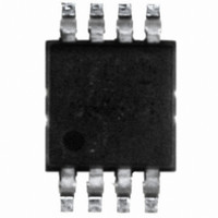
DS620U+T&R Maxim Integrated Products, DS620U+T&R Datasheet - Page 5

DS620U+T&R
Manufacturer Part Number
DS620U+T&R
Description
IC THERMOMETER/STAT DIG 8MSOP
Manufacturer
Maxim Integrated Products
Datasheet
1.DS620U.pdf
(15 pages)
Specifications of DS620U+T&R
Function
Thermometer, Thermostat
Topology
ADC (Sigma Delta), Register Bank
Sensor Type
Internal
Sensing Temperature
-55°C ~ 125°C
Output Type
I²C™/SMBus™
Output Alarm
No
Output Fan
No
Voltage - Supply
1.7 V ~ 3.5 V
Operating Temperature
-55°C ~ 125°C
Mounting Type
Surface Mount
Package / Case
8-MSOP Exposed Pad, 8-HMSOP, 8-eMSOP
Full Temp Accuracy
+/- 2 C
Digital Output - Bus Interface
Serial (2-Wire)
Digital Output - Number Of Bits
13 bit
Maximum Operating Temperature
+ 125 C
Minimum Operating Temperature
- 55 C
Lead Free Status / RoHS Status
Lead free / RoHS Compliant
Figure 2. Timing Diagram
Table 1. Register Summary
TEMPERATURE MEASUREMENT
The DS620 measures temperature using a bandgap-based temperature sensor. A delta-sigma, analog-to-digital
converter (ADC) converts measured temperature to a 10-, 11-, 12-, or 13-bit (user-selectable) digital value that is
calibrated in °C; for °F applications, a lookup table or conversion routine must be used. Throughout this data sheet,
the term “conversion” is used to refer to the entire temperature measurement and ADC sequence.
The DS620 can be configured to power up either automatically converting temperature or in a low-power standby
state. The preferred power-up mode can be set using the AUTOC bit in the configuration register as explained in
the Configuration Register section of this data sheet.
The DS620 can be programmed to perform continuous consecutive conversions (continuous conversion mode) or
to perform single conversions on command (one-shot mode). The conversion mode is programmed through the
1SHOT bit in the configuration register as explained in the Configuration Register section of this data sheet. In
continuous conversion mode, conversions are performed after a Start Convert command is issued (or upon power-
up if the AUTOC bit in the configuration register is set to 1) until a Stop Convert command is issued, at which time
the device goes into a low-power standby state. Continuous conversions can be restarted at any time using the
Start Convert command. In one-shot mode, the DS620 performs a single temperature conversion either at power-
up (if AUTOC = 1) or when a Start Convert command is issued (if AUTOC = 0). When the conversion is complete,
T
Size: 2-Bytes
Note that the 3 LSbs are always “don’t cares” for writes
(i.e., they are not saved) and always read out as 0s.
Configuration Register
Size: 2-Bytes
Temperature Register
Size: 2-Bytes
H
and T
L
Registers
Parameter
5 of 15
EEPROM
Factory State:
TH = 15ºC (0000 0111 1000 0000) [0780h]
TL = 10ºC (0000 0101 0000 0000) [0500h]
SRAM and EEPROM. See Figure 4 and Table 5 for
detailed information and power-up/factory state.
SRAM
(1110 0010 0000 0000) [E200h]
Power-Up State: -60ºC
Information


