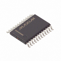
DS1780E Maxim Integrated Products, DS1780E Datasheet - Page 20

DS1780E
Manufacturer Part Number
DS1780E
Description
IC CPU PERIPHERAL MON 24-TSSOP
Manufacturer
Maxim Integrated Products
Datasheet
1.DS1780E.pdf
(28 pages)
Specifications of DS1780E
Function
Thermal Monitor, CPU Peripherals
Topology
ADC (Sigma Delta), Comparator, Fan Speed Control, Register Bank
Sensor Type
Internal
Sensing Temperature
-40°C ~ 125°C
Output Type
I²C™/SMBus™
Output Alarm
No
Output Fan
Yes
Voltage - Supply
2.8 V ~ 5.75 V
Operating Temperature
-40°C ~ 125°C
Mounting Type
Surface Mount
Package / Case
24-TSSOP
Full Temp Accuracy
+/- 12 %
Digital Output - Bus Interface
Serial (2-Wire)
Digital Output - Number Of Bits
8 bit
Maximum Operating Temperature
+ 125 C
Minimum Operating Temperature
- 40 C
Lead Free Status / RoHS Status
Contains lead / RoHS non-compliant
Available stocks
Company
Part Number
Manufacturer
Quantity
Price
Company:
Part Number:
DS1780E
Manufacturer:
MAX
Quantity:
3 000
Part Number:
DS1780E
Manufacturer:
DALLAS
Quantity:
20 000
Part Number:
DS1780E+T&R
Manufacturer:
MAXIM/美信
Quantity:
20 000
Company:
Part Number:
DS1780E+TR
Manufacturer:
MAXIM
Quantity:
1 001
Company:
Part Number:
DS1780E-TR
Manufacturer:
ICS
Quantity:
933
Company:
Part Number:
DS1780E/TR
Manufacturer:
XILINX
Quantity:
17
TEMPERATURE CONFIGURATION REGISTER (ADDRESS Ox4B; POWER-UP
DEFAULT = 01h) Table 10.12
TEST REGISTER (ADDRESS 0x15h; POWER-UP DEFAULT = 00h)
Table 10.13
ANALOG OUTPUT (ADDRESS 0x19h; POWER-UP DEFAULT = FFh)
Table 10.14
BIT
ADDRESS <A7:0A>h
ADDRESS <A7:0A>h
2-6
0
1
7
Temperature
Temperature
mode select
mode select
Reserved
Temp [0]
Interrupt
Interrupt
NAME
Bit 0
Bit 1
15h
19h
Hot
Hot
R/W
R/W
R/W
R/W
R
Ninth bit of the temperature (Value = 0.5°C).
If Bits 0 and Bits 1 of this register are both 0 or both 1, this selects the default interrupt
mode which gives the user an interrupt if the temperature goes above the hot limit. The
interrupt will be cleared once the status register is read, but it will again be generated when
the next conversion has completed. It will continue to do so until the temperature goes
below the hysteresis limit.
A 0 on Bit 1 and a 1 on Bit 0 selects the one-time interrupt mode which gives the user an
indefinite interrupt when it goes above the hot limit. The interrupt will be cleared once the
status register is read. Another interrupt will not be generated until the temperature first goes
below the hysteresis limit. It will also be cleared if the status register is read. No more
interrupts will be generated until the temperature goes above the hot limit again. The
corresponding bit will be cleared in the status register every time it is read but may not set
again when the next conversion is done.
A 1 on this bit (Bit 1) and a 0 on Bit 0 selects the comparator mode. This gives an SMI
when the temperature exceeds the hot limit. This SMI remains active until the status register
is read or the temperature goes below the hot limit (no hysteresis), when the SMI will
become inactive.
Default = 00000.
Note 3
R/W
R/W
R/W
Power-up Default = 00h
Power-up Default = FFh. No other reset affects this register. FFh
value set analog out to MAX value = 1.25V.
20 of 28
DESCRIPTION
DESCRIPTION
DESCRIPTION


