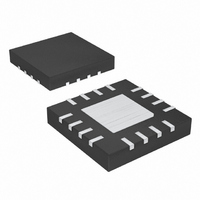
MAX6639ATE+ Maxim Integrated Products, MAX6639ATE+ Datasheet - Page 16

MAX6639ATE+
Manufacturer Part Number
MAX6639ATE+
Description
IC TEMP MONITOR 2CH 16-TQFN
Manufacturer
Maxim Integrated Products
Datasheet
1.MAX6639AEE.pdf
(22 pages)
Specifications of MAX6639ATE+
Function
Fan Control, Temp Monitor
Topology
ADC, PWM Generator, Tach Counter
Sensor Type
External & Internal
Sensing Temperature
0°C ~ 150°C, External Sensor
Output Type
I²C™/SMBus™
Output Alarm
Yes
Output Fan
Yes
Voltage - Supply
3 V ~ 3.6 V
Operating Temperature
-40°C ~ 125°C
Mounting Type
Surface Mount
Package / Case
16-TQFN Exposed Pad
Lead Free Status / RoHS Status
Lead free / RoHS Compliant
2-Channel Temperature Monitor with Dual,
Automatic, PWM Fan-Speed Controller
D[7:6]: This sets the number of tachometer pulses per
revolution for the fan. When set properly, a 2000RPM fan
with two pulses per revolution has the same tachometer
count as a 2000RPM fan with four pulses per revolution.
Table 10 lists tachometer pulses per revolution.
D[5:0]: This sets the minimum allowable fan tachometer
count (maximum speed). This limits the maximum
speed of the fan to reduce noise at high temperatures.
For reasonable speed resolution, the fan RPM range
should be set so this value is between approximately
30 and 60. If a maximum RPM limit is unnecessary, this
value can be set to the full-speed tachometer count.
These registers contain the present value of the PWM
duty cycle. In PWM fan-control mode, the desired (tar-
get) value of the PWM duty cycle can be written directly
into this register.
Table 10. Tachometer Pulses per
Revolution
Figure 6. High-Side PWM Drive Circuit
16
REGISTERS 24h
OR 25h D[7:6]
______________________________________________________________________________________
Fan 1 and 2 Pulses and Min RPM (24h and 25h)
00
01
10
11
Fan 1 and 2 Duty Cycle (26h and 27h)
V
CC
PWM1
TACH1
TACHOMETER PULSES PER
4.7kΩ
4.7kΩ
3V TO 5.5V
OUTPUT
REVOLUTION
TACH
1
2
3
4
(5V OR 12V)
V
FAN
These registers contain the temperatures at which fan
control begins (in automatic RPM mode).
A variety of fan-drive circuit configurations can be used
with the MAX6639 to control the fan’s speed. Four of
the most common are shown in Figures 6 through 10.
The simplest way to control the speed of a 3-wire (sup-
ply, ground, and tachometer output) fan is to modulate
its power supply with a PWM signal. The PWM frequen-
cy is typically in the 20Hz to 40Hz range, with 33Hz
being a common value. If the frequency is too high, the
fan’s internal control circuitry does not have sufficient
time to turn on during a power-supply pulse. If the fre-
quency is too low, the power-supply modulation
becomes more easily audible.
The PWM can take place on the high side (Figure 6) or
the low side (Figure 7) of the fan’s power supply. In
either case, if the tachometer is used, it is usually nec-
essary to periodically stretch a PWM pulse so there is
enough time to count the tachometer pulse edges for
speed measurement. The MAX6639 allows this pulse
stretching to be enabled or disabled to match the
needs of the application.
Pulse stretching can sometimes be audible if the fan
responds quickly to changes in the drive voltage. If the
acoustic effects of pulse stretching are too noticeable,
Figure 7. Low-Side Drive Circuit
PWM Power-Supply Drive (High Side or Low Side)
Channel 1 and Channel 2 Fan-Start Temperature
Applications Information
V
CC
TACH1
PWM1
4.7kΩ
4.7kΩ
3V TO 5.5V
3V TO 5.5V
OUTPUT
TACH
Fan-Drive Circuits
(5V OR 12V)
V
FAN
(28h and 29h)


