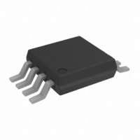
AD7740KRMZ Analog Devices Inc, AD7740KRMZ Datasheet - Page 2

AD7740KRMZ
Manufacturer Part Number
AD7740KRMZ
Description
IC CONV SYNC VOLT-FREQ 8-MSOP
Manufacturer
Analog Devices Inc
Type
Voltage to Frequencyr
Datasheet
1.AD7740YRMZ.pdf
(11 pages)
Specifications of AD7740KRMZ
Frequency - Max
500kHz
Full Scale
±50ppm/°C
Linearity
±0.012%
Mounting Type
Surface Mount
Package / Case
8-TSSOP, 8-MSOP (0.118", 3.00mm Width)
Frequency
1MHz
Full Scale Range
500kHz
Linearity %
1%
Supply Voltage Range
3V To 5.25V
Digital Ic Case Style
SOIC
No. Of Pins
8
Msl
MSL 3 - 168 Hours
Frequency Max
1MHz
Converter Function
VFC
Full Scale Frequency
1000
Power Supply Requirement
Single
Single Supply Voltage (max)
5.25V
Single Supply Voltage (min)
3V
Dual Supply Voltage (typ)
Not RequiredV
Dual Supply Voltage (min)
Not RequiredV
Dual Supply Voltage (max)
Not RequiredV
Operating Temperature (min)
0C
Operating Temperature (max)
85C
Operating Temperature Classification
Commercial
Package Type
MSOP
Converter Type
Voltage/Frequency
Rohs Compliant
Yes
Lead Free Status / RoHS Status
Lead free / RoHS Compliant
Lead Free Status / RoHS Status
Lead free / RoHS Compliant, Lead free / RoHS Compliant
Available stocks
Company
Part Number
Manufacturer
Quantity
Price
Part Number:
AD7740KRMZ
Manufacturer:
ADI/亚德诺
Quantity:
20 000
Company:
Part Number:
AD7740KRMZ-REEL7
Manufacturer:
ADI
Quantity:
1 000
Company:
Part Number:
AD7740KRMZ-REEL7
Manufacturer:
NXP
Quantity:
6 000
Part Number:
AD7740KRMZ-REEL7
Manufacturer:
ADI原装
Quantity:
20 000
AD7740 SPECIFICATIONS
Parameter
DC PERFORMANCE
ANALOG INPUT, VIN
REFERENCE VOLTAGE
FOUT OUTPUT
LOGIC INPUTS (CLKIN, BUF)
LOGIC OUTPUTS (FOUT, CLKOUT)
POWER REQUIREMENTS
NOTES
1
2
3
4
5
6
7
8
Specifications subject to change without notice.
Temperature range: K Version, 0°C to +85°C; Y Version, –40°C to +105°C; typical specifications are at 25°C.
See Terminology.
Guaranteed by design and characterization, not production tested.
Span = Max output frequency–Min output frequency.
Because this pin is bidirectional, any external reference must be capable of sinking/sourcing 400 µA in order to overdrive the internal reference.
These logic levels apply to CLKOUT only when it is loaded with one CMOS load.
Operation at VDD = 2.7 V is also possible with degraded specifications.
Outputs unloaded. I
type (see Clock Generation section).
Integral Nonlinearity
Offset Error
Gain Error
Offset Error Drift
Gain Error Drift
Power Supply Rejection Ratio
Nominal Input Span
Input Current
REFIN
REFOUT
Reference Drift
Line Rejection
Line Rejection
Reference Noise (0.1 Hz to 10 Hz)
Nominal Frequency Span
CLKIN
BUF
Output High Voltage, V
Output High Voltage, V
Output Low Voltage, V
V
I
I
I
Power-Up Time
DD
DD
DD
DD
CLKIN = 32 kHz
CLKIN = 1 MHz
CLKIN = 32 kHz
CLKIN = 1 MHz
Nominal Input Voltage
Output Voltage
Output Impedance
Input Frequency
Input High Voltage, V
Input High Voltage, V
Input Low Voltage, V
Input Low Voltage, V
Input Current
Pin Capacitance
Input High Voltage, V
Input High Voltage, V
Input Low Voltage, V
Input Low Voltage, V
Input Current
Pin Capacitance
7
(Normal Mode)
(Normal Mode)
(Power-Down)
5
2
3
3
DD
3
3
3
3
increases by C
8
8
3
3
3
OL
OH
OH
IL
IL
IL
IL
IH
IH
IH
IH
L
3
× V
3
OUT
3
× f
3
FOUT
Min
0.1
32
3.5
2.5
2.4
2.1
4.0
2.1
3.0
2.3
when FOUT is loaded. If using a crystal/resonator as the clock source, I
0.1 f
K, Y Versions
CLKIN
Typ
± 7
± 7
± 0.1
± 20
± 4
–55
–65
0 – V
8
5
2.5
2.5
1
± 50
–75
–60
100
3
3
0.1
0.9
1.1
30
30
(VDD = 3.0 V to 3.6 V, 4.75 V to 5.25 V, GND = 0 V, REFIN = 2.5 V; CLKIN = 1 MHz; All
specifications T
to 0.9 f
REF
Max
± 0.012
± 0.012
± 0.018
± 0.018
± 35
± 35
± 0.7
VDD – 0.2
10
100
VDD
2.7
1000
0.8
0.4
± 2
10
0.8
0.4
± 100
10
0.4
5.25
1.25
1.5
100
1
CLKIN
MIN
to T
Unit
% of Span
% of Span
% of Span
% of Span
mV
mV
% of Span
µV/°C
ppm of Span/°C
dB
dB
V
V
µA
nA
V
V
kΩ
ppm/°C
dB
dB
µV p–p
Hz
kHz
V
V
V
V
µA
pF
V
V
V
V
nA
pF
V
V
V
V
mA
mA
µA
µs
MAX
unless otherwise noted.)
4
Test Conditions/Comments
Unbuffered Mode, External Clock at CLKIN
Unbuffered Mode, Crystal at CLKIN
Buffered Mode, External Clock at CLKIN
Buffered Mode, Crystal at CLKIN
Unbuffered Mode, VIN = 0 V
Buffered Mode, VIN = 0.1 V
∆VDD = ± 5% (5 V)
∆VDD = ± 10% (3.3 V)
± 150 mV Overrange Available
Buffered Mode
Unbuffered Mode, VIN = 5.4 V, REFIN = 5.25 V
Buffered Mode, VIN = 0.1 V, REFIN = 2.5 V
See Pin Function Description
∆VDD = ± 5% (5 V)
∆VDD = ± 10% (3.3 V)
VIN = 0 V to V
For Specified Performance
VDD = 5 V ± 5%
VDD = 3.3 V ± 10%
VDD = 5 V ± 5%
VDD = 3.3 V ± 10%
VIN = 0 V to V
VDD = 5 V ± 5%
VDD = 3.3 V ± 10%
VDD = 5 V ± 5%
VDD = 3.3 V ± 10%
Output Sourcing 200 µA
Output Sourcing 200 µA
Output Sinking 1.6 mA
V
V
Exiting Power-Down (Ext. Clock at CLKIN)
IH
IH
= VDD, V
= VDD, V
DD
will vary depending on the crystal/resonator
IL
IL
REF
DD
= GND. Unbuffered Mode
= GND. Buffered Mode
. See Figure 2
6
6
6
. VDD = 5 V ± 5%
. VDD = 3.3 V ± 10%


