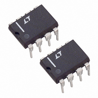
LT1460ACN8-2.5 Linear Technology, LT1460ACN8-2.5 Datasheet - Page 15

LT1460ACN8-2.5
Manufacturer Part Number
LT1460ACN8-2.5
Description
IC PREC SERIES REF MICRPWR 8-DIP
Manufacturer
Linear Technology
Datasheet
1.LT1460EIS8-5.pdf
(26 pages)
Specifications of LT1460ACN8-2.5
Reference Type
Series
Voltage - Output
2.5V
Tolerance
±0.075%
Temperature Coefficient
10ppm/°C
Voltage - Input
3.4 ~ 20 V
Number Of Channels
1
Current - Quiescent
130µA
Current - Output
40mA
Operating Temperature
0°C ~ 70°C
Mounting Type
Through Hole
Package / Case
8-DIP (0.300", 7.62mm)
Lead Free Status / RoHS Status
Contains lead / RoHS non-compliant
Current - Cathode
-
Available stocks
Company
Part Number
Manufacturer
Quantity
Price
Part Number:
LT1460ACN8-2.5#PBF
Manufacturer:
LINEAR/凌特
Quantity:
20 000
applications inForMation
Longer Battery Life
Series references have a large advantage over older shunt
style references. Shunt references require a resistor from
the power supply to operate. This resistor must be chosen
to supply the maximum current that can ever be demanded
by the circuit being regulated. When the circuit being
controlled is not operating at this maximum current, the
shunt reference must always sink this current, resulting
in high dissipation and short battery life.
The LT1460 series reference does not require a current set-
ting resistor and can operate with any supply voltage from
V
not demand current, the LT1460 reduces its dissipation and
battery life is extended. If the reference is not delivering load
current it dissipates only a few mW, yet the same configura-
tion can deliver 20mA of load current when demanded.
Capacitive Loads
The LT1460 is designed to be stable with capacitive loads.
With no capacitive load, the reference is ideal for fast set-
tling, applications where PC board space is a premium,
or where available capacitance is limited.
The test circuit for the LT1460-2.5 shown in Figure 1 is
used to measure the response time for various load cur-
rents and load capacitors. The 1V step from 2.5V to 1.5V
produces a current step of 1mA or 100µA for R
R
with no load capacitance.
The reference settles to 2.5mV (0.1%) in less than 1µs
for a 100µA pulse and to 0.1% in 1.5µs with a 1mA step.
When load capacitance is greater than 0.01µF , the refer-
ence begins to ring due to the pole formed with the output
impedance. Figure 3 shows the response of the reference
to a 1mA and 100µA load current step with a 0.01µF load
capacitor. The ringing can be greatly reduced with a DC
load as small as 200µA. With large output capacitors, ≥1µF ,
OUT
L
= 10k. Figure 2 shows the response of the reference
V
+ 0.9V to 20V. When the circuitry being regulated does
IN
= 5V
0.1µF
C
IN
Figure 1. Response Time Test Circuit
LT1460-2.5
V
OUT
C
L
R
L
V
GEN
L
1460 F01
2.5V
1.5V
= 1k or
the ringing can be reduced with a small resistor in series
with the reference output as shown in Figure 4. Figure 5
shows the response of the LT1460-2.5 with a R
V
IN
= 5V
0.1µF
C
IN
V
V
V
V
V
V
V
V
V
GEN
OUT
OUT
GEN
OUT
OUT
GEN
OUT
OUT
Figure 4. Isolation Resistor Test Circuit
Figure 5. Effect of R
LT1460-2.5
Figure 3. C
Figure 2. C
0.1ms/DIV
20µs/DIV
1µs/DIV
L
= 0.01µF
R
L
S
S
= 0
for C
V
OUT
L
C
L
R
= 1µF
L
1460 F02
1460 F03
1460 F05
LT1460
V
GEN
2.5V
1.5V
R
R
2.5V
1.5V
R
R
2.5V
1.5V
R
R
R
R
S
L
L
L
L
L
S
L
S
= 1k
= 1k
= 10k
= 1k
= 10k
= 1k
= 0
= 2
= 2Ω and
1460 F04
2.5V
1.5V
1460fc


