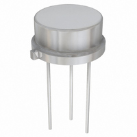
LT1031BMH Linear Technology, LT1031BMH Datasheet - Page 6

LT1031BMH
Manufacturer Part Number
LT1031BMH
Description
IC PREC REF 10V 5PPM/DEGC TO39-3
Manufacturer
Linear Technology
Datasheet
1.LT1031DCH.pdf
(12 pages)
Specifications of LT1031BMH
Reference Type
Series
Voltage - Output
10V
Tolerance
±0.05%
Temperature Coefficient
5ppm/°C
Voltage - Input
4.5 ~ 40 V
Number Of Channels
1
Current - Quiescent
1.7µA
Current - Output
10mA
Operating Temperature
-55°C ~ 125°C
Mounting Type
Through Hole
Package / Case
TO-39-3, TO-205AD, Metal Can
Lead Free Status / RoHS Status
Contains lead / RoHS non-compliant
Current - Cathode
-
Available stocks
Company
Part Number
Manufacturer
Quantity
Price
Company:
Part Number:
LT1031BMH
Manufacturer:
LT
Quantity:
5 510
Company:
Part Number:
LT1031BMH/883Q
Manufacturer:
LT
Quantity:
8
APPLICATIO S I FOR ATIO
Trimming Output Voltage
The LT1031 output can be trimmed by driving the ground
pin. The suggested method is shown in the illustration
below. A 5Ω resistor is inserted in series with the ground
pin. The top of the resistor is supplied current from a trim
potentiometer. This technique requires fairly high trim
current of up to 1.5mA from the LT1031 or 3.5mA from the
–15V supply; however it is necessary to maintain low drift
in the reference. Ground pin current changes in the LT1031,
with temperature, could be as high as 4µA/°C. This,
coupled with the 5Ω external resistor, creates up
to 2ppm/°C drift in the reference (5Ω • 4µA/°C = 20µV/°C
= 2ppm/°C). If induced drift higher than this can be
tolerated, all resistor values in the trim circuit can be raised
proportionately to reduce current drain.
LT1031/LH0070
6
TYPICAL PERFOR A CE CHARACTERISTICS
V
**INCREASE TO 10Ω FOR LT1031D
Output Voltage Trimming
IN
*CAN BE INCREASED TO 5.6k FOR
LT1031B AND LH0070-2
U
IN
U
LT1031
GND
W
R1**
5Ω
OUT
U
R2*
4.3k
W
–15V
LT1031 • TA04
R3
50k
V
OUT
0
Output Noise 0.1Hz to 10Hz
U
FILTERING = 1 ZERO AT 0.1Hz
10µV (1ppm)
1
2 POLES AT 10Hz
2
TIME (MINUTES)
3
Effect of Reference Drift on System Accuracy
A large portion of the temperature drift error budget in
many systems is the system reference voltage. The graph
below indicates the maximum temperature coefficient
allowable if the reference is to contribute no more than
1/2LSB error to the overall system performance. The
example shown is a 12-bit system designed to operate
over a temperature range from 25°C to 65°C. Assuming
the system calibration is performed at 25°C, the
temperature span is 40°C. The graph shows that the
temperature coefficient of the reference must be no worse
than 3ppm/°C if it is to contribute less than 1/2LSB error.
For this reason, the LT1031 has been optimized for low
drift.
4
LT1031 • TPC16
5
100
1.0
10
Maximum Allowable Reference Drift
6
10
14-BIT
20
TEMPERATURE SPAN (°C)
30
12-BIT
40
10-BIT
50
8-BIT
60
70
80
LT1031 • TA03
90
100
1031fb


