ECJ-RVC1H100F Panasonic - ECG, ECJ-RVC1H100F Datasheet - Page 2
ECJ-RVC1H100F
Manufacturer Part Number
ECJ-RVC1H100F
Description
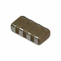
CAP ARRAY 10PF 50V NP0 1206
Manufacturer
Panasonic - ECG
Series
ECJ-Rr
Datasheets
1.ECJ-RVB1H332M.pdf
(4 pages)
2.ECJ-RVB1H332M.pdf
(6 pages)
3.ECJ-RVB1H332M.pdf
(2 pages)
4.ECJ-RVB1H332M.pdf
(1 pages)
5.ECJ-RVB1H332M.pdf
(3 pages)
Specifications of ECJ-RVC1H100F
Capacitance
10pF
Voltage - Rated
50V
Dielectric Material
Ceramic
Number Of Capacitors
4
Circuit Type
Isolated
Temperature Coefficient
C0G, NP0
Tolerance
±1pF
Mounting Type
Surface Mount
Package / Case
1206 (3216 Metric)
Height
0.033" (0.85mm)
Size / Dimension
0.126" L x 0.063" W (3.20mm x 1.60mm)
Lead Free Status / RoHS Status
Lead free / RoHS Compliant
Other names
ECJ-RVC1H100D
ECJRVC1H100D
ECJRVC1H100F
P10580TR
ECJRVC1H100D
ECJRVC1H100F
P10580TR
Available stocks
Company
Part Number
Manufacturer
Quantity
Price
Company:

Part Number:
ECJ-RVC1H100F
Manufacturer:
Panasonic - ECG
Quantity:
135


■
● Class 1
Temperature coeffi cient: calculated between 20 °C to 85 °C
● Class 2
For applicable “temperature characteristics”, see the lists of standard products on page 31 to 32.
■
■
■
■
✽ Standard condition: Temperature 15 to 35 °C, Relative humidity 45 to 75 %.
For further information, see the technical specifi cations.
Design and specifi cations are each subject to change without notice. Ask factory for the current technical specifi cations before purchase and/or use.
Should a safety concern arise regarding this product, please be sure to contact us immediately.
Operating
Temperature
Range
Dielectric
Withstanding
Voltage
Insulation
Resistance (IR)
Capacitance
Q Factor or
Dissipation Factor
(tan δ)
Characteristic Code
Characteristic Code
Temperature Characteristics
Rated Voltage
Nominal Capacitance
Capacitance tolerance
Specifi cations and Testing Methods
Rated Voltage
Capacitance
Class
Temperature
Temperature
Nominal
1
2
Code
Item
Ex.
C
B
F
CH
Temp. Char.
No dielectric breakdown and/or damage
10000 M
Note: 100/C (M ) min. for DC 10 V max.
Within the specifi ed tolerance
Q:
CH: –55 to 125 °C
C: Nominal Cap. in µF
C < 30 pF: Q >400+20 C
30 pF<C <1000 pF:
C: Nominal Cap. in pF
Characteristics
Capacitance range
Temperature
Q >1000
DC 50 V
Temperature Characteristics
Characteristics
1H
CH
10 pF
Temperature
Class 1
or 500/C (M ) Whichever is less
100
B, X7R, X5R
X7R
X5R
Y5V
B
F
F, Y5V
Temp. Coeff.
Specifi cations
(ppm/°C)
0 ± 60
DC 25 V
1E
Temp. Char.
tan δ:
Please see the technical
specifi cations for details.
Capacitance Change
C=10 pF
C>10 pF
B, X7R: –55 to 125 °C
X5R: –55 to 85 °C
F, Y5V: –30 to 85 °C
Temp. Char.
+30, –80 %
100 pF
+22, –82 %
B, X7R: 0.025 max.
X5R: 0.075 max.
F, Y5V: 0.125 max.
– EC29 –
101
±10 %
±15 %
±15 %
Class 2
Multilayer Ceramic Capacitors(4 Array Type)
max.
0.49
Rate of Capacitance change at each Temp. (%)
DC 16 V
–25 °C
1C
Tolerance Code
Temperature Range
–55 to 125 °C
100,000 pF
–0.27
Measurement
–25 to 85 °C
–55 to 85 °C
–25 to 85 °C
min.
–30 to 85 °C
M
K
(0.1 µF)
F
Z
Test voltage:
Duration: 1 to 5 s
Charge/discharge current: 50 mA max.
Measuring voltage: Rated voltage
Duration: 60±5 s
Charge/discharge current: 50 mA max.
Measuring temperature: 20±2 °C
Preconditioning: The capacitors shall be
kept in temperature of 150 +0/–10 ± for 1
hour and subject to standard conditions
for 48±4 hours before initial measurement.
Measuring frequency
Measuring frequency
104
Class 1: Rated voltage
Class 2: Rated voltage
Class 1
Measuring voltage
Class 2
Measuring voltage
DC 10 V
1A
Test Method
max.
0.39
Capacitance Tolerance
———
Reference Temperature
+80, –20 %
1,000,000 pF
85 °C
±20 %
±10 %
±1 pF
1 MHz ± 10 %
(1.0 µF)
1 kHz ± 10 %
1.0±0.2 Vrms
0.5 to 5 Vrms
20 °C
25 °C
25 °C
20 °C
25 °C
DC 6.3 V
105
300 %
250 %
00 Sep. 2008
0J
–0.39
min.
✽
Related parts for ECJ-RVC1H100F
Image
Part Number
Description
Manufacturer
Datasheet
Request
R

Part Number:
Description:
CAP ARRAY 3300PF 50V X7R 1206
Manufacturer:
Panasonic - ECG
Datasheet:
Part Number:
Description:
CAP ARRAY 4700PF 50V X7R 1206
Manufacturer:
Panasonic - ECG
Datasheet:
Part Number:
Description:
CAP ARRAY 6800PF 50V X7R 1206
Manufacturer:
Panasonic - ECG
Datasheet:
Part Number:
Description:
CAP ARRAY 68PF 50V NP0 1206
Manufacturer:
Panasonic - ECG
Datasheet:
Part Number:
Description:
CAP ARRAY 150PF 50V NP0 1206
Manufacturer:
Panasonic - ECG
Datasheet:
Part Number:
Description:
CAP ARRAY 1UF 10V Y5V 1206
Manufacturer:
Panasonic - ECG
Datasheet:
Part Number:
Description:
CAP ARRAY 330PF 50V NP0 1206
Manufacturer:
Panasonic - ECG
Datasheet:
Part Number:
Description:
CAP ARRAY 470PF 50V NP0 1206
Manufacturer:
Panasonic - ECG
Datasheet:
Part Number:
Description:
CAP ARRAY 330PF 50V X7R 1206
Manufacturer:
Panasonic - ECG
Datasheet:
Part Number:
Description:
CAP ARRAY 12PF 50V NP0 1206
Manufacturer:
Panasonic - ECG
Datasheet:


Part Number:
Description:
MICROPHONE OMNI 6X2.2MM W/CAP
Manufacturer:
Panasonic - ECG
Datasheet:

Part Number:
Description:
CAP .01UF 100V PEN FILM 1210 5%
Manufacturer:
Panasonic - ECG
Datasheet:

Part Number:
Description:
FILTER LINE 23.3MH 2A
Manufacturer:
Panasonic - ECG
Datasheet:

Part Number:
Description:
SAW FILTER PCS 1960 MHZ 50/150
Manufacturer:
Panasonic - ECG
Datasheet: