GNM212R61A225MA01D Murata Electronics North America, GNM212R61A225MA01D Datasheet - Page 93
GNM212R61A225MA01D
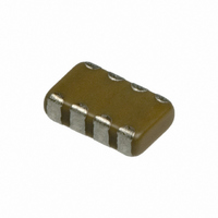
Manufacturer Part Number
GNM212R61A225MA01D
Description
CAP 2-ARRAY 2.2UF 10V X5R 0805
Manufacturer
Murata Electronics North America
Series
GNMr
Datasheet
1.GNM212R61A225MA01D.pdf
(151 pages)
Specifications of GNM212R61A225MA01D
Capacitance
2.2µF
Voltage - Rated
10V
Dielectric Material
Ceramic
Number Of Capacitors
2
Circuit Type
Isolated
Temperature Coefficient
X5R
Tolerance
±20%
Mounting Type
Surface Mount
Package / Case
0805 (2012 Metric)
Height
0.033" (0.85mm)
Size / Dimension
0.079" L x 0.049" W (2.00mm x 1.25mm)
Lead Free Status / RoHS Status
Lead free / RoHS Compliant
Other names
GNM212R61A225MA01


!Note
• This PDF catalog is downloaded from the website of Murata Manufacturing co., ltd. Therefore, it’s specifications are subject to change or our products in it may be discontinued without advance notice. Please check with our
• This PDF catalog has only typical specifications because there is no space for detailed specifications. Therefore, please approve our product specifications or transact the approval sheet for product specifications before ordering.
sales representatives or product engineers before ordering.
!Note
3. Adhesive Curing
4. Flux Application
5. Flow Soldering
1. Resin Coating
2. Circuit Design
Inverting the PCB
When selecting resin materials, select those with
low contraction.
These capacitors in this catalog are not safety
recognized products
An excessive amount of flux generates a large quantity of
Flux containing too high a percentage of halide may
Set temperature and time to ensure that leaching of the
Others
Insufficient curing of the adhesive causes chips to
disconnect during flow soldering and causes deteriorated
insulation resistance between outer electrodes due to
moisture absorption.
Control curing temperature and time in order to prevent
insufficient hardening.
Make sure not to impose an abnormal mechanical shock on
the PCB.
flux gas, causing deteriorated solderability. So apply flux
thinly and evenly throughout. (A foaming system is
generally used for flow soldering).
cause corrosion of the outer electrodes unless sufficiently
outer electrode does not exceed 25% of the chip end
area as a single chip (full length of the edge A-B-C-D
shown below) and 25% of the length A-B shown below as
mounted on substrate.
Continued from the preceding page.
(Reference Data 6. Thermal shock)
(Reference Data 7. Solder heat resistance)
• Please read rating and !CAUTION (for storage, operating, rating, soldering, mounting and handling) in this catalog to prevent smoking and/or burning, etc.
• This catalog has only typical specifications because there is no space for detailed specifications. Therefore, please approve our product specifications or transact the approval sheet for product specifications before ordering.
3. Remarks
The above notices are for standard applications and
conditions. Contact us when the products are used
in special mounting conditions. Select optimum
conditions for operation as they determine the
reliability of the product after assembly.
The data herein are given in typical values, not
guaranteed ratings.
[As a Single Chip]
[As Mounted on Substrate]
cleaned. Use flux with a halide content of 0.2wt% max.
But do not use strong acidic flux.
Wash thoroughly because water soluble flux causes
deteriorated insulation resistance between outer
electrodes unless sufficiently cleaned.
B
C
A
B
A
D
Outer Electrode
Notice
C02E.pdf
91
07.2.6
13
Related parts for GNM212R61A225MA01D
Image
Part Number
Description
Manufacturer
Datasheet
Request
R

Part Number:
Description:
BUZZER PIEZO 25VP-P SMD
Manufacturer:
Murata Electronics North America

Part Number:
Description:
CAP 4-ARRAY 680PF 100V X7R 1206
Manufacturer:
Murata Electronics North America
Datasheet:
Part Number:
Description:
CAP 4-ARRAY 1000PF 100V X7R 1206
Manufacturer:
Murata Electronics North America
Datasheet:
Part Number:
Description:
CAP 4-ARRAY 1800PF 100V X7R 1206
Manufacturer:
Murata Electronics North America
Datasheet:
Part Number:
Description:
CAP 4-ARRAY 68000PF 16V X7R 1206
Manufacturer:
Murata Electronics North America
Datasheet:

Part Number:
Description:
CAP CER 1000PF 50V 10% X7R 0402
Manufacturer:
Murata Electronics North America
Datasheet:
Part Number:
Description:
CAP CER 10000PF 16V 10% X7R 0402
Manufacturer:
Murata Electronics North America
Datasheet:

Part Number:
Description:
CAP 5.5-25PF 2.5X3.2MM SMD
Manufacturer:
Murata Electronics North America
Datasheet:

Part Number:
Description:
CAP 4.5-20PF 2.5X3.2MM SMD
Manufacturer:
Murata Electronics North America
Datasheet:

Part Number:
Description:
CAP 5.0-20PF 3.2X4.5MM SMD RED
Manufacturer:
Murata Electronics North America
Datasheet:

Part Number:
Description:
CAP 2.0-6.0PF 3.2X4.5MM SMD BLU
Manufacturer:
Murata Electronics North America
Datasheet:

Part Number:
Description:
CAP 1.4-3.0PF 3.2X4.5MM SMD BRN
Manufacturer:
Murata Electronics North America
Datasheet:

Part Number:
Description:
CAP 3.0-10PF 3.2X4.5MM SMD WHT
Manufacturer:
Murata Electronics North America
Datasheet:

Part Number:
Description:
CAP 2.0-6.0PF 4X4.5MM TOPADJ BLU
Manufacturer:
Murata Electronics North America
Datasheet:

Part Number:
Description:
CAP 8.5-40PF 4X4.5MM TOPADJ YEL
Manufacturer:
Murata Electronics North America
Datasheet: