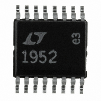
LT1952EGN#PBF Linear Technology, LT1952EGN#PBF Datasheet - Page 17

LT1952EGN#PBF
Manufacturer Part Number
LT1952EGN#PBF
Description
IC CTLR PWM SGL SWITCH 16-SSOP
Manufacturer
Linear Technology
Datasheet
1.LT1952EGNPBF.pdf
(24 pages)
Specifications of LT1952EGN#PBF
Pwm Type
Current Mode
Number Of Outputs
1
Frequency - Max
560kHz
Duty Cycle
90%
Voltage - Supply
9.25 V ~ 25 V
Buck
No
Boost
No
Flyback
Yes
Inverting
No
Doubler
No
Divider
No
Cuk
No
Isolated
Yes
Operating Temperature
-40°C ~ 125°C
Package / Case
16-SSOP
Frequency-max
560kHz
Number Of Pwm Outputs
1
On/off Pin
No
Adjustable Output
No
Topology
Flyback/Forward
Switching Freq
80 TO 560kHz
Operating Supply Voltage (max)
25V
Synchronous Pin
Yes
Rise Time
50ns
Fall Time
30ns
Operating Temperature Classification
Automotive
Mounting
Surface Mount
Pin Count
16
Package Type
SSOP N
Lead Free Status / RoHS Status
Lead free / RoHS Compliant
Available stocks
Company
Part Number
Manufacturer
Quantity
Price
APPLICATIONS INFORMATION
(A) V
(B) SD_V
(C) OC < 107mV, and
(D) SS_MAXDC < 0.45V (SS_MAXDC reset threshold)
*V
was only set by overcurrent condition in (3) above.
SS_MAXDC Discharge Timing
It can be seen in Figure 10 that two types of discharge
can occur for the SS_MAXDC pin. In timing (A) the fault
that caused the soft-start event has been removed before
SS_MAXDC falls to 0.45V. This means the soft-start
latch will be reset when SS_MAXDC falls to 0.45V and
SS_MAXDC will begin charging. In timing (B), the fault that
caused the soft-start event is not removed until some time
after SS_MAXDC has fallen past 0.45V. The SS_MAXDC
pin continues to discharge to 0.2V and remains low until
all faults are removed.
The time for SS_MAXDC to fall to a given voltage can be
approximated as:
where:
For faults arising from (1) and (2),
For a fault arising from (3),
IN
SS_MAXDC (t
(C
I
C
SS_MAXDC(DC) = programmed DC voltage
V
recharge
I
V
V
SS_MAXDC(DC) = V
V
(if fault removed before t
DIS
DIS
SS
SS(MIN)
REF
REF
SS(MIN)
> 8.75V (6.5V LT1952-1) is ok for latch reset if the latch
SS
IN
~ 8e
= net discharge current on C
= capacitor value at SS_MAXDC pin
/I
> 14.25* (7.75V LT1952-1), and
= 100mV.
= 2.5V.
DIS
SEC
–4
) • [SS_MAXDC(DC) – V
= minimum SS_MAXDC voltage before
= SS_MAXDC reset threshold = 0.45V
> 1.32V, and
+ (V
FALL
REF
) =
– V
REF
SS(MIN)
[R
FALL
B
/(R
)
)[(1/2R
T
+ R
SS
SS(MIN)
B
)]
B
) – (1/R
]
T
)]
Example:
If the OC fault is not removed before 185μs then SS_MAXDC
will continue to fall past 0.45V towards a new V
The typical V
SS_MAXDC Charge Timing
When all faults are removed and the SS_MAXDC pin
has fallen to its reset threshold of 0.45V or lower, the
SS_MAXDC pin will be released and allowed to charge.
SS_MAXDC will rise until it settles at its programmed DC
voltage—setting the maximum switch duty cycle clamp.
The calculation of charging time for the SS_MAXDC pin
between any two voltage levels can be approximated as
an RC charging waveform using the model shown in
Figure 11.
The ability to predict SS_MAXDC rise time between any two
voltages allows prediction of several key timing periods:
(1)No Switching Period
(2)Converter Output Rise Time
(3)Time For Maximum Duty Cycle Clamp within X% of
The time for SS_MAXDC to charge to a given voltage V
is found by re-arranging:
For an overcurrent fault (OC > 100mV), V
R
V
I
= 8e
SS_MAXDC(DC) = 1.84V
SS_MAXDC (t
= 1.85e–4 s
(time from SS_MAXDC(DC) to V
V
(time from V
level of SS_MAXDC where maximum duty cycle
clamp equals the natural duty cycle of the switch)
Target Value
DIS
T
SS(MIN)
SS(MIN)
= 35.7k, R
~ 8e
–4
+ (2.05)(–0.23e
–4
= 0.45V,
to V
OL
+ (2.5 – 0.45)[(1/2 • 100k) – (1/35.7k)]
SS(ACTIVE)
for SS_MAXDC at 150μA is 0.2V.
SS(ACTIVE)
B
FALL
= 100k, C
) = (1e – 7/7.5e
LT1952/LT1952-1
)
to V
–4
SS
) = 7.5e
SS(REG)
= 0.1μF and assume
SS(MIN)
–4
–4
; V
) • (1.84 – 0.45)
SS(REG)
+ time from
REF
is the
= 2.5V,
SS(MIN)
17
19521fd
SS
.


