DPA424R Power Integrations, DPA424R Datasheet - Page 9
DPA424R
Manufacturer Part Number
DPA424R
Description
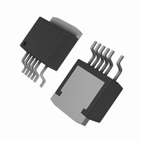
IC CONV DC-DC DPA SWITCH TO263-7
Manufacturer
Power Integrations
Series
DPA-Switch®r
Specifications of DPA424R
Applications
Converter, Power Over Ethernet and Telecom Applications
Voltage - Input
16 ~ 75 V
Number Of Outputs
1
Voltage - Output
220V
Operating Temperature
-40°C ~ 125°C
Mounting Type
Surface Mount
Package / Case
D²Pak, TO-263 (6 leads + tab, variant)
Output Voltage
9 V
Output Current
3.5 A
Input Voltage
- 0.3 V to + 220 V
Switching Frequency
282 KHz to 425 KHz
Operating Temperature Range
- 40 C to + 150 C
Mounting Style
SMD/SMT
Duty Cycle (max)
79 %
For Use With
DAK-21A - KIT DESIGN ACCELERATOR DPA SW
Lead Free Status / RoHS Status
Contains lead / RoHS non-compliant
Available stocks
Company
Part Number
Manufacturer
Quantity
Price
Company:

Part Number:
DPA424R
Manufacturer:
POWER
Quantity:
15 000
Part Number:
DPA424R
Manufacturer:
POWER
Quantity:
20 000
Company:
Part Number:
DPA424R-TL
Manufacturer:
ON
Quantity:
4 300
Company:
Part Number:
DPA424R-TL
Manufacturer:
PI
Quantity:
520
Part Number:
DPA424R-TL
Manufacturer:
POWER
Quantity:
20 000


LINE-SENSE (L) Pin Operation
When current is fed into the LINE-SENSE pin, it works as a
voltage source of approximately 2.6 V up to a maximum current
of +240 μA (typical). At +240 μA, this pin turns into a constant
current sink. Refer to Figure 8. In addition, a comparator with a
threshold of 1 V is connected at the pin and is used to detect
when the pin is shorted to the SOURCE pin.
There are a total of fi ve functions available through the use of
the LINE-SENSE pin: OV, UV, line feed-forward with DC
reduction, remote ON/OFF and synchronization. Shorting the
LINE-SENSE pin to the SOURCE pin disables all fi ve functions.
The LINE-SENSE pin is typically used for line sensing by
connecting a resistor from this pin to the positive input DC
voltage bus to implement OV, UV and line feed-forward with
DC
resistor determines the line OV/UV thresholds, and the DC
reduced linearly with input DC high voltage starting from just
above the UV threshold. This pin can also be used as the input
pin for remote ON/OFF and synchronization. An external
transistor placed between the LINE-SENSE pin and the
CONTROL pin realizes remote ON/OFF via UV or OV threshold.
Synchronization is available by connecting an open drain
external MOSFET between the LINE-SENSE pin and the
SOURCE pin to generate synchronization pulse. Each time the
MOSFET turns on, the falling edge of the LINE-SENSE pin
voltage initiates a new switching cycle. The lowest
synchronization frequency guaranteed by DPA-Switch is
128 kHz. Refer to Table 2 for possible combinations of the
functions with example circuits shown in Figure 11 through
Figure 24. A description of specifi c functions in terms of the
LINE-SENSE pin I/V characteristic is shown in Figure 7 (right
hand side). The horizontal axis represents LINE-SENSE pin
current with positive polarity indicating currents fl owing into the
pin. The meaning of the vertical axes varies with functions. For
www.powerint.com
MAX
reduction over line voltage. In this mode, the value of the
MAX
MAX
is
those that control the on/off states of the output such as UV,
OV and remote ON/OFF, the vertical axis represents the enable/
disable states of the output. UV triggers at I
(+50 μA typical with 4 μA hysteresis) and OV triggers at I
μA typical with 4 μA hysteresis). Between the UV and OV
thresholds, the output is enabled. For line feed-forward with
DC
the DC
maximum duty cycle from 75% at I
at I
EXTERNAL CURRENT LIMIT (X) Pin Operation
When current is drawn out of the EXTERNAL CURRENT LIMIT pin,
it works as a voltage source of approximately
1.3 V up to a maximum current of -230 μA (typical). At
-230 μA, it turns into a constant current source (refer to Figure 8).
There are two functions available through the use of the
EXTERNAL CURRENT LIMIT pin: external current limit and
remote ON/OFF. Shorting the EXTERNAL CURRENT LIMIT pin
and SOURCE pin disables both functions. In high effi ciency
applications, this pin can be used to reduce the current limit
externally to a value close to the operating peak current, by
connecting the pin to the SOURCE pin through a resistor. The
pin can also be used as a remote ON/OFF control input.
Table 2 shows several different ways of using this pin. See
Figure 7 for a description of the functions where the horizontal
axis (left hand side) represents the EXTERNAL CURRENT LIMIT
pin current. The meaning of the vertical axes varies with
function. For those that control the on/off states of the output
such as remote ON/OFF, the vertical axis represents the enable/
disable states of the output. For external current limit, the
vertical axis represents the magnitude of the I
graphs in the Typical Performance Characteristics section for
the current limit programming range and the selection of the
appropriate resistor value.
OV
MAX
(+135 μA).
reduction, the vertical axis represents the magnitude of
MAX
Line feed-forward with DC
DPA422-426
L(DC)
MAX
(+55 μA typical) to 33%
reduction lowers
UV
LIMIT
. Please see
Rev. S 12/07
OV
(+135
9
Related parts for DPA424R
Image
Part Number
Description
Manufacturer
Datasheet
Request
R

Part Number:
Description:
SOP-16
Manufacturer:
Power Integrations
Datasheet:
Part Number:
Description:
DIP8
Manufacturer:
Power Integrations
Datasheet:
Part Number:
Description:
TO-263
Manufacturer:
Power Integrations
Datasheet:
Part Number:
Description:
TO-263
Manufacturer:
Power Integrations
Datasheet:
Part Number:
Description:
Manufacturer:
Power Integrations
Datasheet: