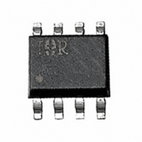
IRU3033CS International Rectifier, IRU3033CS Datasheet - Page 10

IRU3033CS
Manufacturer Part Number
IRU3033CS
Description
IC CTRL/REG PWM SWITCH 8-SOIC
Manufacturer
International Rectifier
Datasheet
1.IRU3033CSTR.pdf
(12 pages)
Specifications of IRU3033CS
Applications
Controller, Intel Pentium®, II, P55C
Voltage - Input
12V
Number Of Outputs
1
Voltage - Output
2 ~ 3.5 V
Operating Temperature
0°C ~ 70°C
Mounting Type
Surface Mount
Package / Case
8-SOIC (3.9mm Width)
Lead Free Status / RoHS Status
Contains lead / RoHS non-compliant
Other names
*IRU3033CS
IRU3033-CS
IRU3033-CS
IRU3033-CS
IRU3033-CS
Available stocks
Company
Part Number
Manufacturer
Quantity
Price
Part Number:
IRU3033CS
Manufacturer:
IR
Quantity:
20 000
Part Number:
IRU3033CSDTR
Manufacturer:
IR
Quantity:
20 000
Part Number:
IRU3033CSTR
Manufacturer:
IR
Quantity:
20 000
IRU3033(PbF)
For example, if Rt=1K and R
ripple is:
The advantage of fixed output ripple is that when the
output voltage changes from 2V to 3.5V, the ripple volt-
age remains the same which is important in meeting the
Intel maximum tolerance specification.
Switcher Output Voltage Setting
The output voltage of the switcher can be set using the
following equations:
Assuming, Vo=3.38V and the selected output ripple is
1.3%(44mV) of the output voltage, a set of equations
are derived that selects the resistor divider and the hys-
teresis resistor.
Assuming, Rt=1KΩ, 1%:
Assuming, ∆Vo=44mV:
The bottom resistor of the divider is then calculated us-
ing the following equations:
10
∆Vo = (1/422)×11 = 26mV
R
Where:
Rt = Top resistor of the resistor divider.
R
and 4 of the IRU3033.
∆Vo = Selected output ripple (typically 1% to 2% of
output voltage).
R
Select R
R
Where:
R
V
X = (Vo +
X = (3.38 +
R
Select R
REF
H
H
H
B
B
B
= Bottom resistor of the divider
= Hysteresis resistor connected between pins 3
= (11×1000) / 0.044 = 250KΩ
= Rt / X
= 1000 / 1.72 = 580Ω
= (11×Rt) / ∆V
= 1.25V typical
H
B
= 576Ω, 1%
= 249KΩ, 1%
∆Vo
0.044
2
2
)/V
)/1.25 - 1 = 1.72
REF
- 1
B
=422K, then the output
www.irf.com
Frequency Calculation
The IRU3033 frequency of operation is calculated using
the following formula:
For our example:
The ESR=18mΩ for 2 of the Sanyo 1500µF, 6MV1500GX
caps. If L=3.5µH then, Fs is calculated as follows:
Fs = (Vo×(1 - D)×ESR) / (L×∆Vo)
D (Vo + Vf) / V
D = (3.38 + 0.5) / 5 = 0.78
Fs =
Fs = 87KHz
Where:
Vo = Output voltage (V)
D = Duty cycle
ESR = Output capacitor ESR
L = Output inductance (µH)
∆Vo = Output ripple voltage (V)
Where:
Vf = Forward voltage drop of the Schottky diode.
(3.38 × (1 - 0.78) × 0.018)
(3.5 × 0.044)
IN
(V)
= 0.087MHz
(MHz)


