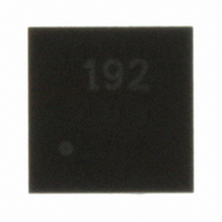
SC192IMLTRT Semtech, SC192IMLTRT Datasheet

SC192IMLTRT
Specifications of SC192IMLTRT
Available stocks
Related parts for SC192IMLTRT
SC192IMLTRT Summary of contents
Page 1
... Space-saving Micro Lead-Frame Package MLPD-10 3x3 Applications Cell Phones Cordless Phones Notebook and Subnotebook Computers PDAs and Mobile Communicators 1 Li-Ion or 3 NiMH/NiCd Powered Devices SC192 9 LX VIN EN 5 ADJ ILIM 10 PGND 7 BP SYNC/PWM R8 4 GND COMP 1 SC192 L1 Vout = 0.75V to Vin www.semtech.com ...
Page 2
... Tied to PCB with 1 square inch, 2 ounce copper. Note: This device is ESD sensitive. Use of ESD handling precautions is required. Electrical Characteristics Unless otherwise noted: VIN = 3.6V, SYNC/PWM = VIN, ILIM = VIN VIN © 2007 Semtech Corp θ =-40 to 85°C. Typical values are PRELIMINARY -0.3 to 7.5 -0 ...
Page 3
... Notes: (1) Load regulation limits are specified from 0 to 700mA. This specification is calculated based on parameters measured individually and is not a tested parameter. See the load regulation limit graph on page 13 for more detailed view of performance. © 2007 Semtech Corp. =-40 to 85°C. Typical values are ...
Page 4
... TOP VIEW VIN GND 3 COMP 4 T ADJ 5 MLPD-10: 3X3 10 LEAD Pin Descriptions © 2007 Semtech Corp. Ordering Information PGND Note (1) Only available in tape and reel packaging. A reel contains 7 SYNC/PWM 3000 devices. 6 ILIM (2) Lead free product. This product is fully WEEE and RoHS compliant ...
Page 5
... POWER MANAGEMENT Block Diagram BP ILIM and slope SYNC/ generation ADJ EN © 2007 Semtech Corp. - Plimit amp + Control logic - PW M comp + - Error amp + 750mV SC192 VIN + Current amp - Nlimit comp - www.semtech.com ...
Page 6
... GND on the output and improve inrush cur- rent control during start-up. © 2007 Semtech Corp. Forced PWM If SYNC/PWM is DC high, the forced PWM mode is en- abled. This ensures that the switching frequency of the converter is maintained over the full range of output loads ...
Page 7
... POWER MANAGEMENT Evaluation Board Schematic TP1 VIN VIN TP3 COMP 10uF 0.1uF 470pF R8 28k TP2 GND GND © 2007 Semtech Corp. VIN R6 1k TP8 ILIM TP4 VIN PGND 10uH 3 8 GND COMP SY NC 47pF 5 6 ADJ ILIM SC192 R3 100k 7 SC192 TP7 ...
Page 8
... POWER MANAGEMENT Evaluation Board Gerber Plots TOP COPPER TOP SILKSCREEN © 2007 Semtech Corp. BOTTOM COPPER BOTTOM SILKSCREEN 8 SC192 PRELIMINARY www.semtech.com ...
Page 9
... Because the SC192 has external compensation the use of small inexpensive ceramic capacitors can be used for the output capacitor allowing the designer greater flexibility. VIN C1 C3 10uF 0.1uF VIN C1 C3 4.7uF 0.1uF © 2007 Semtech Corp. ⎛ ⎞ • ⎟ ⎜ Vout 1 0.75 ⎝ ...
Page 10
... The plots below were taken at Vin = 3.6V, Vout = 1.8V, with the compensation components listed in Table 1. The upper plot is LX, the middle plot is output voltage, the lower plot is the current transient of 0.1A to 0.6A PSAVE, Cout = 20uF, Lout = 10uH PSAVE, Cout = 10uF, Lout = 10uH © 2007 Semtech Corp ...
Page 11
... V Δ = • ⎜ • ⎟ ⎜ ⎟ ⎝ ⎠ © 2007 Semtech Corp. PWM, Cout = 4.7uF, Lout = 4.7uH f = Switching frequency L = Inductor Value ΔI = Peak-to-peak inductor ripple current Maximum inductor current Output voltage OUT V = Input voltage Output Capacitance OUT ...
Page 12
... Be aware of the high cur- rent paths and avoid tying signal grounds to the high power grounds where the signal paths might experience large fluctuations in voltages as high currents pass though copper traces. © 2007 Semtech Corp. 0.45 I • OUT ...
Page 13
... O Temp ( C) Shutdown Current vs Temperature 0.9 0.8 0.7 0.6 0.5 0.4 0.3 0.2 0 Temperature ( © 2007 Semtech Corp 2.5V 4.5 4.7 4.9 IN 760 755 Vin = 2.7 V 750 Vin = 3.6V 745 Vin = 5.5V 740 735 730 725 720 715 710 80 100 120 ...
Page 14
... Outline Drawing - MLPD-10 PIN 1 INDICATOR (LASER MARK) aaa C LxN NOTES: 1. CONTROLLING DIMENSIONS ARE IN MILLIMETERS (ANGLES IN DEGREES). 2. COPLANARITY APPLIES TO THE EXPOSED PAD AS WELL AS TERMINALS. Marking Information Top Marking 192 yyww yy = two-digit year of manufacture ww = two-digit week of manufacture © 2007 Semtech Corp SEATING PLANE bxN bbb ...
Page 15
... POWER MANAGEMENT Land Pattern - MLPD-10 ( NOTES: 1. THIS LAND PATTERN IS FOR REFERENCE PURPOSES ONLY. CONSULT YOUR MANUFACTURING GROUP TO ENSURE YOUR COMPANY'S MANUFACTURING GUIDELINES ARE MET. Contact Information © 2007 Semtech Corp. DIMENSIONS DIM INCHES (.112 .075 H .055 .087 P .020 X .012 Y Y .037 Z ...


