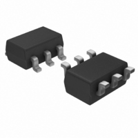
TC1220ECHTR Microchip Technology, TC1220ECHTR Datasheet - Page 5

TC1220ECHTR
Manufacturer Part Number
TC1220ECHTR
Description
IC CHARGE PUMP CONV SD SOT23A-6
Manufacturer
Microchip Technology
Type
Switched Capacitor (Charge Pump), Doubler, Invertingr
Datasheet
1.TC1220ECHTR.pdf
(16 pages)
Specifications of TC1220ECHTR
Internal Switch(s)
Yes
Synchronous Rectifier
No
Number Of Outputs
1
Voltage - Output
-2.5 ~ -5.5 V, ±5 ~ ±11 V
Current - Output
25mA
Frequency - Switching
35kHz
Voltage - Input
2.5 ~ 5.5 V
Operating Temperature
-40°C ~ 85°C
Mounting Type
Surface Mount
Package / Case
SOT-23-6
Power - Output
240mW
Primary Input Voltage
5.5V
No. Of Outputs
1
Output Current
25mA
No. Of Pins
6
Operating Temperature Range
-40°C To +85°C
Peak Reflow Compatible (260 C)
Yes
Switching Frequency Max
35kHz
Function
Inverting, Step Up
Output Voltage
- 2.5 V to - 5.5 V, 5 V to 11 V
Maximum Operating Temperature
85 C
Minimum Operating Temperature
- 40 C
Mounting Style
SMD/SMT
Lead Free Status / RoHS Status
Lead free / RoHS Compliant
Lead Free Status / RoHS Status
Lead free / RoHS Compliant, Lead free / RoHS Compliant
Available stocks
Company
Part Number
Manufacturer
Quantity
Price
Part Number:
TC1220ECHTR
Manufacturer:
MICROCHIP/微芯
Quantity:
20 000
4.0
4.1
The TC1219/TC1220 perform voltage conversion but
do not provide regulation. The output voltage will droop
in a linear manner with respect to load current. The
value of this equivalent output resistance is approxi-
mately 25Ω nominal at +25°C and V
approximately -5V at light loads, and droops according
to the equation below:
V
V
4.2
The overall power efficiency of the charge pump is
affected by four factors:
1.
2.
3.
4.
Most of the conversion losses are due to factors (2) and
(3) above. These losses are given by Equation 4-1(b).
EQUATION 4-1:
The 1/(f
effective output resistance of an ideal switched
capacitor circuit (Figure 4-1 and Figure 4-2). The value
of R
TC1219/TC1220.
2002 Microchip Technology Inc.
OUT
DROP
a) P
b) where R
Losses from power consumed by the internal
oscillator, switch drive, etc. (which vary with
input
frequency).
I
MOSFET switches on-board the charge pump.
Charge pump capacitor losses due to effective
series resistance (ESR).
Losses that occur during charge transfer (from
the commutation capacitor to the output
capacitor) when a voltage difference between
the two capacitors exists.
SWITCH
2
= – (V
R losses due to the on-resistance of the
= I
LOSS
APPLICATIONS INFORMATION
Output Voltage Considerations
Charge Pump Efficiency
OSC
OUT
IN
voltage,
)(C1) term in Equation 4-1(b) is the
(2, 3)
can be approximated at 0.5Ω for the
x R
– V
OUT
DROP
OUT
4ESR
= I
=
OUT
[
temperature
1 / [f
)
C
2
1
x R
OSC
+ ESR
OUT
(C1) ] + 8R
C
2
]
IN
and
= +5V. V
SWITCH
oscillator
OUT
+
is
The remaining losses in the circuit are due to factor (4)
above, and are shown in Equation 4-2. The output
voltage ripple is given by Equation 4-3.
EQUATION 4-2:
EQUATION 4-3:
FIGURE 4-1:
FIGURE 4-2:
V
RIPPLE
V +
P
V +
LOSS (4)
(C
R
EQUIV
= [ I
2
)(V
C1
R
OUT
RIPPLE
EQUIV
TC1219/TC1220
=
=
[
f x C1
f
/ 2 x ( f
(0.5)(C1)(V
1
2
– 2V
IDEAL SWITCHED
CAPACITOR MODEL
EQUIVALENT OUTPUT
RESISTANCE
OSC
OUT
) (C2)] + 2 ( I
C2
C2
IN
2
V
– V
RIPPLE
OUT
DS21366B-page 5
)
R
2
]
OUT
R
) + (0.5)
L
x f
L
V
OSC
) (ESR
V
OUT
OUT
C2
)


