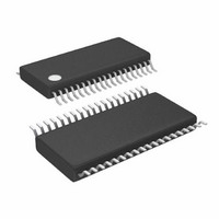
LTC3865EFE#PBF Linear Technology, LTC3865EFE#PBF Datasheet - Page 20

LTC3865EFE#PBF
Manufacturer Part Number
LTC3865EFE#PBF
Description
IC BUCK SYNC ADJ DUAL 38TSSOP
Manufacturer
Linear Technology
Type
Step-Down (Buck)r
Datasheet
1.LTC3865EUHPBF.pdf
(38 pages)
Specifications of LTC3865EFE#PBF
Internal Switch(s)
No
Synchronous Rectifier
Yes
Number Of Outputs
2
Voltage - Output
0.6 ~ 5 V
Frequency - Switching
250kHz ~ 770kHz
Voltage - Input
4.5 ~ 38 V
Operating Temperature
-40°C ~ 85°C
Mounting Type
Surface Mount
Package / Case
38-TSSOP Exposed Pad, 38-eTSSOP, 38-HTSSOP
Primary Input Voltage
15V
No. Of Outputs
2
Output Voltage
5V
Output Current
25A
No. Of Pins
38
Operating Temperature Range
-40°C To +85°C
Msl
MSL 1 - Unlimited
Rohs Compliant
Yes
Lead Free Status / RoHS Status
Lead free / RoHS Compliant
Current - Output
-
Power - Output
-
Available stocks
Company
Part Number
Manufacturer
Quantity
Price
LTC3865/LTC3865-1
APPLICATIONS INFORMATION
shown in Figure 6a. In this tracking mode, V
be set higher than V
tracking, the ratio of the V
the same as the master channel’s internal feedback divider.
By selecting different resistors, the LTC3865/LTC3865-1
can achieve different modes of tracking including the two
in Figure 5.
So which mode should be programmed? The coincident
mode offers better output regulation. This can be better
understood with the help of Figure 7. At the input stage
of the slave channel’s error amplifi er, two common an-
ode diodes are used to clamp the equivalent reference
20
TK/SS2
V
OUT1
PIN
TO
OUT2
nR3
nR4
(5a) Coincident Tracking
. To implement the ratiometric
OUT2
(6a) Coincident Tracking Setup
TIME
divider should be exactly
R1
R2
Figure 5. Two Different Modes of Output Voltage Tracking
Figure 6. Setup for Coincident and Ratiometric Tracking
TO
EA1
Figure 7. Equivalent Input Circuit of Error Amplifi er
TK/SS2
EA2
TO
0.6V
V
FB2
V
V
OUT1
OUT1
OUT2
R3
R4
D1
V
OUT2
must
I
D2
I
D3
voltage and an additional diode is used to match the shifted
common mode voltage. The top two current sources are
of the same magnitude. In coincident mode, the TK/SS
voltage is substantially higher than 0.6V at steady state and
effectively turns off D1. D2 and D3 will therefore conduct
the same current and offer tight matching between V
and the internal precision 0.6V at steady state. In the
ratiometric mode, however, TK/SS equals 0.6V at steady
state. D1 will divert part of the bias current to make V
slightly lower than 0.6V. Although this error is minimized
by the exponential I-V characteristics of the diode, it does
impose a fi nite amount of output voltage deviation.
+
–
TK/SS2
V
OUT1
EA2
PIN
TO
nR1
nR2
(6b) Ratiometric Tracking Setup
3865 F07
R1
R2
(5b) Ratiometric Tracking
TO
EA1
EA2
TIME
TO
R3
R4
38551
V
OUT2
F06
3865
V
V
F05
OUT1
OUT2
3865fb
FB2
FB2


