MCP1256-IMF Microchip Technology, MCP1256-IMF Datasheet - Page 13
MCP1256-IMF
Manufacturer Part Number
MCP1256-IMF
Description
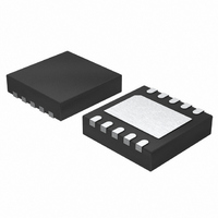
IC CHARGE PUMP DC/DC CONV 10DFN
Manufacturer
Microchip Technology
Type
Step-Up (Boost), Switched Capacitor (Charge Pump)r
Specifications of MCP1256-IMF
Internal Switch(s)
Yes
Synchronous Rectifier
No
Number Of Outputs
1
Voltage - Output
3.3V
Current - Output
100mA
Frequency - Switching
650kHz
Voltage - Input
1.8 ~ 3.6 V
Operating Temperature
-40°C ~ 125°C
Mounting Type
Surface Mount
Package / Case
10-DFN
For Use With
MCP1256/7/8/9EV - BOARD EVAL FOR MCP1256/7/8/9
Lead Free Status / RoHS Status
Lead free / RoHS Compliant
Power - Output
-


4.6
For the MCP1256/8 devices, the PGOOD output is an
open-drain output that sinks current when the regulator
output voltage falls below 0.93V
ulator output voltage falls below 0.93V
less than 200 μs and then recovers, glitch immunity cir-
cuits prevent the PGOOD signal from transitioning low.
A 10 k to 1 M pull-up resistor from PGOOD to V
may be used to provide a logic output. If not used,
connect PGOOD to GND or leave unconnected.
PGOOD is high impedance when the output voltage is
in regulation. A logic low is asserted when the output
falls 7% (typical) below the nominal value. The PGOOD
output remains low until V
its nominal value. On start-up, this pin indicates when
the output voltage reaches its final value. PGOOD is
high impedance when SHDN is low or when BYPASS
is low (MCP1258).
4.7
For the MCP1257/9 devices, the LBO output is an
open-drain output that sinks current when the input
voltage falls below a preset threshold. If the input volt-
age falls below the preset threshold for less than
200 μs and then recovers, glitch immunity circuits pre-
vent the LBO signal from transitioning low. A 10 k to
1 M
to provide a logic output. If not used, connect LBO to
GND or leave unconnected.
LBO is high impedance when the input voltage is above
the low-battery threshold voltage. A logic low is
asserted when the input falls below the low-battery
threshold voltage. The LBO output remains low until
V
low-battery hysteresis voltage. LBO is high impedance
when SHDN is low or when BYPASS is low
(MCP1259).
4.8
The MCP1256/7/8/9 devices feature fold back short-
circuit protection. This circuitry provides an internal
soft-start function by limiting inrush current during
startup and also limits the output current to 150 mA
(typical), if the output is short-circuited to GND. The
internal soft-start circuitry requires approximately
175 μs, typical, from either initial power-up, release
from Shutdown, or release from BYPASS (MCP1258/9)
for the output voltage to be in regulation.
© 2006 Microchip Technology Inc.
IN
is above the low-battery threshold voltage plus the
pull-up resistor from LBO to V
Power-Good Output (PGOOD)
Low-Battery Output (LBO)
Soft-Start and Short-Circuit
Protection
OUT
is within 3% (typical) of
OUT
(typical). If the reg-
OUT
OUT
may be used
(typical) for
OUT
4.9
The MCP1256/7/8/9 devices feature thermal shutdown
with temperature hysteresis. When the die temperature
exceeds 160°C, the device shuts down. When the die
cools by 15°C, the MCP1256/7/8/9 automatically turns
back on again. If high die temperature is caused by out-
put overload and the load is not removed, the device
will turn on and off resulting in a pulsed output.
5.0
5.1
The style and value of capacitors used with the
MCP1256/7/8/9 family determine several important
parameters, such as output voltage ripple and charge
pump strength. To minimize noise and ripple, it is rec-
ommended that low ESR (0.1 ) capacitors be used for
both C
ceramic and should be 10 μF or higher for optimum
performance.
If the source impedance to V
megahertz, C
somewhat smaller value of C
the recommended 10 μF, but will not be as effective in
preventing ripple on the V
The value of C
age ripple present on V
C
slower turn-on time from shutdown and a higher inrush
current.
The flying capacitors (C
of the charge pump and in order to achieve the maxi-
mum rated output current (100 mA), it is necessary to
have at least 1 μF of capacitance for the flying capaci-
tor. A smaller flying capacitor delivers less charge per
clock cycle to the output capacitor resulting in lower
available output current.
5.2
The MCP1256/7/8/9 devices transfer charge at high
switching frequencies producing fast, high peak, tran-
sient currents. As a result, any stray inductance in the
component layout will produce unwanted noise in the
system. Proper board layout techniques are required to
ensure optimum performance.
OUT
will reduce output ripple at the expense of a
IN
Thermal Shutdown
APPLICATIONS
Capacitor Selection
PCB Layout Issues
and C
IN
OUT
MCP1256/7/8/9
may not be required. Alternatively, a
OUT
controls the amount of output volt-
. These capacitors should be
1
OUT
IN
and C
IN
pin.
IN
. Increasing the size of
is very low, up to several
may be substituted for
2
) control the strength
DS21989A-page 13
Related parts for MCP1256-IMF
Image
Part Number
Description
Manufacturer
Datasheet
Request
R

Part Number:
Description:
BOARD EVAL FOR MCP1256/7/8/9
Manufacturer:
Microchip Technology
Datasheet:

Part Number:
Description:
IC CHARGE PUMP DC/DC CONV 10DFN
Manufacturer:
Microchip Technology
Datasheet:

Part Number:
Description:
IC CHARGE PUMP DC/DC CONV 10MSOP
Manufacturer:
Microchip Technology
Datasheet:
Part Number:
Description:
IC CHARGE PUMP DC/DC CONV 10MSOP
Manufacturer:
Microchip Technology
Datasheet:

Part Number:
Description:
Regulated 3.3V, Low-Ripple Charge Pump with Low-Operating Current SLEEP Mode or BYPASS Mode
Manufacturer:
Microchip Technology
Datasheet:
Part Number:
Description:
Low Noise positive Regulator pump w/low power SLEEP mode, -40C to +85C, 10-MSOP, TUBE
Manufacturer:
Microchip Technology
Datasheet:

Part Number:
Description:
MCP1,5 REC HSG10P
Manufacturer:
Tyco Electronics
Datasheet:


Part Number:
Description:
Manufacturer:
Microchip Technology Inc.
Datasheet:
Part Number:
Description:
Manufacturer:
Microchip Technology Inc.
Datasheet:
Part Number:
Description:
Manufacturer:
Microchip Technology Inc.
Datasheet:
Part Number:
Description:
Manufacturer:
Microchip Technology Inc.
Datasheet: