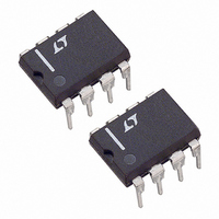
LT1109CN8-5 Linear Technology, LT1109CN8-5 Datasheet - Page 6

LT1109CN8-5
Manufacturer Part Number
LT1109CN8-5
Description
IC DC/DC CONV FIXED OUT 5V 8-DIP
Manufacturer
Linear Technology
Type
Step-Up (Boost)r
Datasheet
1.LT1109CS8-12PBF.pdf
(8 pages)
Specifications of LT1109CN8-5
Internal Switch(s)
Yes
Synchronous Rectifier
No
Number Of Outputs
1
Voltage - Output
5V
Current - Output
100mA
Frequency - Switching
120kHz
Voltage - Input
3V, 5V
Operating Temperature
0°C ~ 70°C
Mounting Type
Through Hole
Package / Case
8-DIP (0.300", 7.62mm)
Power - Output
300mW
Lead Free Status / RoHS Status
Contains lead / RoHS non-compliant
Available stocks
Company
Part Number
Manufacturer
Quantity
Price
Part Number:
LT1109CN8-5#PBF
Manufacturer:
LINEAR/凌特
Quantity:
20 000
LT1109
and-error approach can be used to select the optimum
inductor. Keep in mind the switch current maximum rating
of 1.2A. If the calculated peak current exceeds this, the
input voltage must be increased or the load decreased.
Capacitor Selection
The output capacitor should be chosen on the basis of its
equivalent series resistance (ESR). Surface-mount tanta-
lum electrolytics can be used provided the ESR value is
sufficiently low. An ESR of 0.1 will result in a 50mV step
at the output of the converter when the peak inductor
current is 500mA. Physically larger capacitors have lower
ESR.
Diode Selection
Speed, forward drop, and leakage current are the three
main considerations in selecting a catch diode for LT1109
converters. General purpose rectifiers such as the 1N4001
kept to 600mA or less. Higher switch currents will cause
excessive drop across the switch resulting in reduced
efficiency. In general, switch current should be held to as
low a value as possible in order to keep switch, diode and
inductor losses at a minimum.
As an example, suppose 12V at 60mA is to be generated
from a 4.5V input. Recalling Equation 01,
Energy required from the inductor is
Picking an inductor value of 33 H with 0.2 DCR results
in a peak switch current of
Substituting I
Since 4.77 J > 4 J the 33 H inductor will work. This trial-
6
A
I
PPLICATI
P
F
E
PEAK
L
P
OSC
L
= (12V + 0.5V – 4.5V) (60mA) = 480mW.
L
2
1
1 0
480
4 5
120
33
.
.
PEAK
V
mW
kHz
H
O
1
into Equation 03 results in
0 538
U
–
.
e
S
4 0
– .
.
1 0 4 2
A
I FOR ATIO
33
U
J
2
.
H
.
4 77
s
.
W
J
538
.
m A
.
U
(06)
08
07
09
are unsuitable for use in any switching regulator applica-
tion. Although they are rated at 1A, the switching time of
a 1N4001 is in the 10 s-50 s range. At best, efficiency will
be severely compromised when these diodes are used; at
worst, the circuit may not work at all. Most LT1109 circuits
will be well served by a 1N5818 Schottky diode. The
combination of 500mV forward drop at 1A current, fast
turn-ON and turn-OFF time, and 4 A to 10 A leakage
current fit nicely with LT1109 requirements. At peak
switch currents of 100mA or less, a 1N4148 signal diode
may be used. This diode has leakage current in the 1nA to
5nA range at 25 C and lower cost than a 1N5818.
Table 1. Inductor Manufacturers
MANUFACTURER
Caddell-Burns
258 East Second Street
Mineola, NY 11501
516-746-2310
Coiltronics Incorporated
6000 Park of Commerce Blvd.
Boca Raton, FL 33487
407-241-7876
Coilcraft
1102 Silver Lake Road
Cary, IL 60013
708-639-6400
Sumida Electric Co., Ltd.
637 E. Golf Road, Suite 209
Arlington Heights, IL 60005
708-956-0666
Table 2. Capacitor Manufacturers
MANUFACTURER
Sanyo Video Components
2001 Sanyo Avenue
San Diego, CA 92173
619-661-6835
Matsuo Electronics
2134 Main Street, Suite 200
Huntington Beach, CA 92648
714-969-2491
Kemet Electronics Corporation
Box 5928
Greenville, SC 29606
803-963-6621
Philips Components
2001 W. Blue Heron Blvd.
P.O. Box 10330
Riviera Beach, FL 33404
407-881-3200
PART NUMBERS
T491 Series
49MC Series
OS-CON Series
267 Series
PART NUMBERS
7120 Series
Surface Mount
CTX33-1
DT3316 Series
CD54
CD105
Surface Mount


