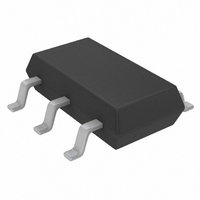
LT1933HS6#TRPBF Linear Technology, LT1933HS6#TRPBF Datasheet

LT1933HS6#TRPBF
Specifications of LT1933HS6#TRPBF
Available stocks
Related parts for LT1933HS6#TRPBF
LT1933HS6#TRPBF Summary of contents
Page 1
... The low current (<2μA) shutdown provides output disconnect, enabling easy power manage- ment in battery-powered systems. L, LT, LTC, LTM, Linear Technology and the Linear logo are registered trademarks of Linear Technology Corporation. ThinSOT is a trademark of Linear Technology Corporation. All other trademarks are the property of their respective owners. ...
Page 2
... EXPOSED PAD (PIN 7) IS GND, MUST BE SOLDERED TO PCB ORDER INFORMATION LEAD FREE FINISH TAPE AND REEL LT1933IDCB#PBF LT1933IDCB#TRPBF LT1933HDCB#PBF LT1933HDCB#TRPBF LT1933ES6#PBF LT1933ES6#TRPBF LT1933IS6#PBF LT1933IS6#TRPBF LT1933HS6#PBF LT1933HS6#TRPBF LEAD BASED FINISH TAPE AND REEL LT1933IDCB LT1933IDCB#TR LT1933HDCB LT1933HDCB#TR LT1933ES6 LT1933ES6#TR LT1933IS6 LT1933IS6#TR LT1933HS6 LT1933HS6#TR Consult LTC Marketing for parts specifi ...
Page 3
ELECTRICAL CHARACTERISTICS temperature range, otherwise specifi cations are at T PARAMETER Undervoltage Lockout Feedback Voltage FB Pin Bias Current Quiescent Current Quiescent Current in Shutdown Reference Line Regulation Switching Frequency Maximum Duty Cycle Switch Current Limit Switch V CESAT Switch ...
Page 4
LT1933 TYPICAL PERFORMANCE CHARACTERISTICS Effi ciency OUT 100 T = 25° OUT 12V 24V MBRM140 L1 = Toko D53LCB 33μ ...
Page 5
TYPICAL PERFORMANCE CHARACTERISTICS Frequency Foldback 700 T = 25°C A 600 500 400 300 200 100 0 0.0 0.5 1.0 FB PIN VOLTAGE (V) 1933 G10 Typical Minimum Input Voltage OUT T = 25° ...
Page 6
LT1933 PIN FUNCTIONS (SOT-23/DFN) BOOST (Pin 1): The BOOST pin is used to provide a drive voltage, higher than the input voltage, to the internal bipolar NPN power switch. GND (Pin 2/Pin 5 and Exposed Pad, Pin 7): Tie the ...
Page 7
OPERATION (Refer to Block Diagram) The LT1933 is a constant frequency, current mode step down regulator. A 500kHz oscillator enables an RS fl ip- fl op, turning on the internal 750mA power switch Q1. An amplifi er and comparator monitor ...
Page 8
... OK, but further reduces maximum load current. For details of maximum output current and discontinuous mode opera- tion, see Linear Technology Application Note 44. Finally, for duty cycles greater than 50 minimum inductance required to avoid subharmonic oscillations. Choosing L greater than 3(V prevents subharmonic oscillations at all duty cycles ...
Page 9
APPLICATIONS INFORMATION switching current into a tight local loop, minimizing EMI. A 2.2μF capacitor is capable of this task, but only placed close to the LT1933 and the catch diode; see the PCB Layout section. A second ...
Page 10
LT1933 APPLICATIONS INFORMATION Figure 1 shows the transient response of the LT1933 with several output capacitor choices. The output is 3.3V. The load current is stepped from 100mA to 400mA and back to 100mA, and the oscilloscope traces show the ...
Page 11
APPLICATIONS INFORMATION BOOST Pin Considerations Capacitor C3 and diode D2 are used to generate a boost voltage that is higher than the input voltage. In most cases a 0.1μF capacitor and fast switching diode (such as the 1N4148 or 1N914) ...
Page 12
LT1933 APPLICATIONS INFORMATION cases the discharged output capacitor will present a load to the switcher which will allow it to start. The plots show the worst-case situation where V is ramping very slowly. IN For lower start-up voltage, the boost ...
Page 13
... LT1933 circuits. However, these capaci- tors can cause problems if the LT1933 is plugged into a live supply (see Linear Technology Application Note 88 for a complete discussion). The low loss ceramic capacitor combined with stray inductance in series with the power ...
Page 14
LT1933 APPLICATIONS INFORMATION CLOSING SWITCH SIMULATES HOT PLUG + LOW IMPEDANCE ENERGIZED 24V SUPPLY + 10μF 35V AI.EI. + 0.1μF Figure 6. A Well Chosen Input Network Prevents Input Voltage Overshoot and Ensures Reliable Operation When the LT1933 is Connected ...
Page 15
APPLICATIONS INFORMATION Figure 6 shows the waveforms that result when an LT1933 circuit is connected to a 24V supply through six feet of 24-gauge twisted pair. The fi rst plot is the response with a 2.2μF ceramic capacitor at the ...
Page 16
LT1933 APPLICATIONS INFORMATION PCB Layout For proper operation and minimum EMI, care must be taken during printed circuit board layout. Figure 8 shows the recommended component placement with trace, ground plane and via locations. Note that large, switched currents fl ...
Page 17
TYPICAL APPLICATIONS 4.5V TO 36V OFF ON 14.5V TO 36V OFF ON 3.3V Step-Down Converter BOOST IN C3 LT1933 0.1μF SHDN SW GND 16. 2.2μF 10k 12V Step-Down Converter D3 ...
Page 18
LT1933 PACKAGE DESCRIPTION 1.65 ±0.05 3.55 ±0.05 (2 SIDES) 2.15 ±0.05 RECOMMENDED SOLDER PAD PITCH AND DIMENSIONS PIN 1 BAR TOP MARK (SEE NOTE 6) 0.200 REF NOTE: 1. DRAWING TO BE MADE A JEDEC PACKAGE OUTLINE M0-229 VARIATION OF ...
Page 19
... PACKAGE EIAJ REFERENCE IS SC-74A (EIAJ) Information furnished by Linear Technology Corporation is believed to be accurate and reliable. However, no responsibility is assumed for its use. Linear Technology Corporation makes no representa- tion that the interconnection of its circuits as described herein will not infringe on existing patent rights. S6 Package ...
Page 20
... LTC3414 4MHz, Synchronous Step-Down DC/DC Converter V OUT LT3430/LT3431 60V, 2.75A I , 200kHz/500kHz, Synchronous Step-Down OUT DC/DC Converter Burst Mode is a registered trademark of Linear Technology Corporation. Linear Technology Corporation 20 1630 McCarthy Blvd., Milpitas, CA 95035-7417 (408) 432-1900 FAX: (408) 434-0507 ● 2.5V Step-Down Converter D2 ...


