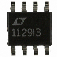
LT1107CS8 Linear Technology, LT1107CS8 Datasheet

LT1107CS8
Specifications of LT1107CS8
Available stocks
Related parts for LT1107CS8
LT1107CS8 Summary of contents
Page 1
... Switch current limit can be programmed with a single resistor. An auxiliary gain block can be configured as a low-battery detector, linear post regulator, undervoltage lock-out circuit, or error amplifier. , LTC and LT are registered trademarks of Linear Technology Corporation L1* MBRS120T3 150mA ...
Page 2
... Step-Down Mode LT1107 (Note 2) LT1107-5 (Note 3) LT1107-12 (Note 3) LT1107 LT1107-5 LT1107-12 Full Load I Tied to V LIM IN ORDER PART NUMBER LT1107CS8 TOP VIEW LT1107CS8-5 8 FB(SENSE)* LT1107CS8-12 7 SET LT1107IS8 AO 6 GND 5 S8 PART MARKING S8 PACKAGE 1107 11075 = 150 C/W JA 110712 1107I MIN TYP MAX ...
Page 3
ELECTRICAL C HARA TERISTICS C temperature range 3V, military or commercial version SYMBOL PARAMETER Feedback Pin Bias Current Set Pin Bias Current V Gain Block Output Low OL Reference Line Regulation A Gain Block Gain V ...
Page 4
LT1107 W U TYPICAL PERFOR A Saturation Voltage, Step-Up Mode (SW2 Pin Grounded) 1 0.6 0.4 0 0.4 0.6 0.8 1.0 1.2 0.2 SWITCH ...
Page 5
W U TYPICAL PERFOR A Minimum/Maximum Frequency vs ON Time, Step-Down Mode 100 – 125 ...
Page 6
LT1107 W BLOCK I D AGRA S LT1107 SET GAIN BLOCK/ ERROR AMP 1.25V REFERENCE A1 OSCILLATOR COMPARATOR GND FB U OPERATIO The LT1107 is a gated oscillator switcher. This type architecture has very low supply ...
Page 7
PPLICATI S I FOR ATIO Inductor Selection –– Step-Up Converter In a step-up, or boost converter (Figure 1), power gener- ated by the inductor makes up the difference between input and output. Power required from the ...
Page 8
LT1107 PPLICATI S I FOR ATIO A where DC = duty cycle (0.50 in step-down mode switch drop in step-down mode diode drop (0.5V for a 1N5818 output current ...
Page 9
PPLICATI S I FOR ATIO A The usual step-up configuration for the LT1107 is shown in Figure 1. The LT1107 first pulls SW1 low causing appear across L1. A current then builds up in ...
Page 10
LT1107 PPLICATI S I FOR ATIO V should be less than 6.2V. More negative output OUT voltages can be accommodated as in the prior section. In Figure 4, the input is negative while the output is ...
Page 11
PPLICATI S I FOR ATIO SWITCH SWITCH Figure 6. Current Limit Keeps Inductor Current Under Control OFF Figure 5. No Current Limit Causes Large Inductor Current Build-Up PROGRAMMED CURRENT LIMIT I ...
Page 12
LT1107 PPLICATI S I FOR ATIO A Figure 7 details current limit circuitry. Sense transistor A1, whose base and emitter are paralleled with power switch Q2, is ratioed such that approximately 0.5% of Q2’s collector current flows ...
Page 13
PACKAGE DESCRIPTIO CORNER LEADS OPTION 0.045 – 0.068 (1.143 – 1.727) FULL LEAD OPTION 0.300 BSC (0.762 BSC) 0.008 – 0.018 (0.203 – 0.457) NOTE: LEAD DIMENSIONS APPLY TO SOLDER DIP/PLATE OR TIN PLATE LEADS U J8 Package 8-Lead CERDIP ...
Page 14
LT1107 PACKAGE DESCRIPTIO .300 – .325 (7.620 – 8.255) .009 – .015 (0.229 – 0.381) +.035 .325 –.015 +0.889 8.255 –0.381 NOTE: 1. DIMENSIONS ARE MILLIMETERS *THESE DIMENSIONS DO NOT INCLUDE MOLD FLASH OR PROTRUSIONS. MOLD FLASH OR PROTRUSIONS SHALL ...
Page 15
... MOLD FLASH OR PROTRUSIONS SHALL NOT EXCEED .006" (0.15mm) Information furnished by Linear Technology Corporation is believed to be accurate and reliable. However, no responsibility is assumed for its use. Linear Technology Corporation makes no represen- tation that the interconnection of its circuits as described herein will not infringe on existing patent rights. ...
Page 16
... A, Can be Used for OUT 65V/75V 6mA <100 A, Can be Used for OUT 28V A/1mA < 28V 100 A/4.8mA <30 A/ 35V/42V 4.5mA <12 A, Can be Used for 35V/42V 4mA <12 A, Can be Used for Q SD LT/TP 1002 1K REV A • PRINTED IN USA LINEAR TECHNOLOGY CORPORATION 1993 1107fa ...


