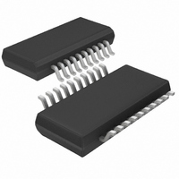
LTC1434IGN#PBF Linear Technology, LTC1434IGN#PBF Datasheet - Page 11

LTC1434IGN#PBF
Manufacturer Part Number
LTC1434IGN#PBF
Description
IC DC/DC CONV STEP-DOWN 20-SSOP
Manufacturer
Linear Technology
Type
Step-Down (Buck)r
Datasheet
1.LTC1433CGN.pdf
(20 pages)
Specifications of LTC1434IGN#PBF
Internal Switch(s)
Yes
Synchronous Rectifier
No
Number Of Outputs
1
Voltage - Output
3.3V, 5V, Adj
Current - Output
450mA
Frequency - Switching
125kHz ~ 240kHz
Voltage - Input
3 ~ 13.5 V
Operating Temperature
-40°C ~ 85°C
Mounting Type
Surface Mount
Package / Case
20-SSOP
Lead Free Status / RoHS Status
Lead free / RoHS Compliant
Power - Output
-
APPLICATIONS
Power-On Reset Function (POR)
The power-on reset function monitors the output voltage
and turns on an open-drain device when it is out of
regulation. An external pull-up resistor is required on the
POR pin.
When power is first applied or when coming out of
shutdown, the POR output is pulled to ground. When the
output voltage rises above a level which is 5% below the
regulated output value, an internal counter starts. After
counting 2
device turns off.
The POR output will go low whenever the output voltage
drops below 7.5% of its regulated value for longer than
approximately 30 s, signaling an out-of-regulation condi-
tion. In shutdown the POR output is pulled low even if the
regulator’s output is held up by an external source.
Run/Soft Start Function
The RUN/SS pin is a dual purpose pin which provides the
soft start function and a means to shut down the LTC1433/
LTC1434. Soft start reduces input surge currents by
providing a gradual ramp-up of the internal current limit.
Power supply sequencing can also be accomplished using
this pin.
An internal 3 A current source charges up an external
capacitor C
the LTC1433/LTC1434 begins operating. As the voltage
on RUN/SS continues to ramp from 1.3V to 2.4V the
internal current limit is also ramped at a proportional
linear rate. The current limit begins at approximately
350mA (at V
2.4V). The output voltage thus ramps up slowly, charging
the output capacitor while input surge currents are re-
duced. If RUN/SS has been pulled all the way to ground
there is a delay of approximately 0.5s/ F before starting,
followed by a like time to reach full current.
By pulling the RUN/SS pin below 1.3V, the LTC1433/
LTC1434 are put in low current shutdown. This pin can be
driven directly from logic as shown in Figure 8. Diode D1
in Figure 8 reduces the start delay but allows C
up slowly providing the soft start function. This diode can
t
DELAY
= 5(10
16
SS.
RUN/SS
(65536) clock cycles the POR pull-down
When the voltage on RUN/SS reaches 1.3V
5
)C
U
SS
= 1.3V) and ends at 1.2A (V
seconds
INFORMATION
U
W
SS
U
RUN/SS
to ramp
=
be deleted if soft start is not needed. The RUN/SS pin has
an internal 6V Zener clamping the voltage on this pin (see
Functional Diagram).
Phase-Locked Loop and Frequency Synchronization
The LTC1434 has an internal voltage-controlled oscilla-
tor and phase detector comprising a phase-locked loop.
This allows the MOSFET turn-on to be locked to the rising
edge of an external source. The frequency range of the
voltage-controlled oscillator is 30% around the center
frequency f
desired operating frequency (f
expression (assuming the phase-locked loop is locked,
i.e V
Instead of using the above expression, Figure 2 graphi-
cally shows the relationship between the oscillator fre-
quency and the value of C
conditions at the PLL LPF pin.
The phase detector used is an edge sensitive digital type
which provides zero degrees phase shift between the
external and internal oscillators. This type of phase detector
will not lock up on input frequencies close to the harmonics
of the V
equal to the capture range, f
The output of the phase detector is a pair of complemen-
tary current sources charging or discharging the external
filter network on the PLL LPF pin. The relationship
between the voltage on the PLL LPF pin and operating
frequency is shown in Figure 9. A simplified block diagram
is shown in Figure 10.
C
OSC
PLL LPF
CO
pF
center frequency. The PLL hold-in range f
O
= 1.19V):
. The value of C
Figure 8. RUN/SS Pin Interfacing
D1
Frequency
RUN/SS
2 06 10
.
LTC1433/LTC1434
C
SS
4
OSC
H
OSC
kHz
= f
O
under various voltage
is calculated from the
) with the following
C
–
= 0.3f
11
RUN/SS
O.
C
1433/34 F08
SS
11
H
is


