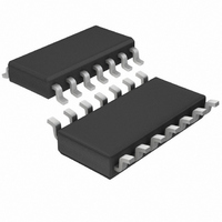
LTC1148CS-5 Linear Technology, LTC1148CS-5 Datasheet - Page 4

LTC1148CS-5
Manufacturer Part Number
LTC1148CS-5
Description
IC SW REG STEP-DOWN 5V 14-SOIC
Manufacturer
Linear Technology
Type
Step-Down (Buck)r
Datasheet
1.LTC1148CSPBF.pdf
(20 pages)
Specifications of LTC1148CS-5
Internal Switch(s)
No
Synchronous Rectifier
Yes
Number Of Outputs
1
Voltage - Output
5V
Current - Output
50mA
Frequency - Switching
250kHz
Voltage - Input
3.5 ~ 20 V
Operating Temperature
0°C ~ 70°C
Mounting Type
Surface Mount
Package / Case
14-SOIC (3.9mm Width), 14-SOL
Lead Free Status / RoHS Status
Contains lead / RoHS non-compliant
Power - Output
-
Available stocks
Company
Part Number
Manufacturer
Quantity
Price
Part Number:
LTC1148CS-5
Manufacturer:
LT/凌特
Quantity:
20 000
LTC1148
LTC1148-3.3/LTC1148-5
Note 1: Absolute Maximum Ratings are those values beyond which the life
of a device may be impaired.
Note 2: T
dissipation P
Note 3: Dynamic supply current is higher due to the gate charge being
delivered at the switching frequency. See Applications Information.
Note 4: The LTC1148 and LTC1148HV versions are tested with external
feedback resistors resulting in a nominal output voltage of 5V. The
LTC1148L version is tested with external feedback resistors resulting in a
nominal output voltage of 2.5V.
TYPICAL PERFOR
ELECTRICAL C
4
100
2.1
1.8
1.5
1.2
0.9
0.6
0.3
LTC1148CN, LTC1148CN-3.3, LTC1148CN-5: T
LTC1148CS, LTC1148CS-3.3, LTC1148CS-5: T
92
80
98
96
94
90
88
86
84
82
0
0
0
Efficiency vs Input Voltage
DC Supply Current
NOT INCLUDING
GATE CHARGE CURRENT
J
2
is calculated from the ambient temperature T
D
4
4
according to the following formulas:
INPUT VOLTAGE (V)
6
I
INPUT VOLTAGE
LOAD
ACTIVE MODE
SLEEP MODE
8
8
= 100mA
10 12 14 16 18
HARA TERISTICS
12
FIGURE 1 CIRCUIT
I
LOAD
LTC1148 • TPC04
LTC1148 • TPC01
W
= 1A
16
A
C
U
20
20
CE
J
J
= T
= T
C
A
A
A
HARA TERISTICS
+ (P
+ (P
–20
–30
–40
and power
–10
20
18
16
14
12
10
40
30
20
10
0
8
6
4
2
0
D
0
0
Supply Current in Shutdown
D
Line Regulation
V
× 110°C/W)
FIGURE 1 CIRCUIT
I
× 70°C/W)
LOAD
SHUTDOWN
2
= 1A
C
4
4
INPUT VOLTAGE (V)
6
INPUT VOLTAGE (V)
= 2V
8
8
10
Note 5: In applications where R
time increases approximately 40%.
Note 6: The LTC1148, LTC1148HV and LTC1148L series are not tested
and not quality assurance sampled at –40°C and 85°C. These
specifications are guaranteed by design and/or correlation. The
LTC1148HVI-5 is guaranteed over the full –40°C to 85°C operating
temperature range.
Note 7: The LTC1148L and LTC1148L-3.3 allow operation to V
12 14 16
12
LTC1148 • TPC05
LTC1148 • TPC02
16
18
20
20
–100
–20
–40
–60
–80
20
1.6
1.4
1.2
1.0
0.8
0.6
0.4
0.2
SENSE
0
0
0
Load Regulation
Operating Frequency
vs (V
0
V
OUT
is placed at ground potential, the off
IN
2
0.5
= 5V
– V
(V
V
IN
V
LOAD CURRENT (A)
IN
OUT
IN
4
– V
= 12V
= 6V
1
OUT
)
) VOLTAGE (V)
6
FIGURE 1 CIRCUIT
R
1.5
25°C
SENSE
0°C
8
70°C
IN
= 0.05Ω
LTC1148 • TPC06
2
LTC1148 • TPC03
= 3.5V.
10
114835fd
2.5
12


