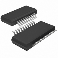
LTC1434IGN#TRPBF Linear Technology, LTC1434IGN#TRPBF Datasheet - Page 8

LTC1434IGN#TRPBF
Manufacturer Part Number
LTC1434IGN#TRPBF
Description
IC DC/DC CONV STEP-DOWN 20-SSOP
Manufacturer
Linear Technology
Type
Step-Down (Buck)r
Datasheet
1.LTC1433CGN.pdf
(20 pages)
Specifications of LTC1434IGN#TRPBF
Internal Switch(s)
Yes
Synchronous Rectifier
No
Number Of Outputs
1
Voltage - Output
3.3V, 5V, Adj
Current - Output
450mA
Frequency - Switching
125kHz ~ 240kHz
Voltage - Input
3 ~ 13.5 V
Operating Temperature
-40°C ~ 85°C
Mounting Type
Surface Mount
Package / Case
20-SSOP
Lead Free Status / RoHS Status
Lead free / RoHS Compliant
Power - Output
-
APPLICATIONS
LTC1433/LTC1434
As the operating frequency is increased the gate charge
losses will be higher, reducing efficiency. The maximum
recommended switching frequency is 700kHz. When us-
ing Figure 2 for synchronizable applications, the value of
C
your center frequency (see Phase-Locked Loop and Fre-
quency Synchronization).
Low Supply Operation
The LTC1433/LTC1434 can function down to 3V and the
maximum allowable output current is also reduced at low
input voltages. Figure 3 shows the amount of change as
the supply is reduced down to 2.5V. The minimum guar-
anteed input supply is 3V.
Another important point to note is that at a low supply
voltages, the R
(see Typical Performance Characteristics). Therefore, the
user should calculate the power dissipation when the
8
Figure 3. Maximum Allowable Output Current vs Supply Voltage
OSC
is selected corresponding to a frequency 30% below
Figure 2. Selecting C
700
600
500
400
300
200
100
100
0
90
80
70
60
50
0
4.0
DS(ON)
V
PLLLPF
CAPACITANCE ON C
U
V
50
PLLLPF
= 0V
of the P-channel switch increases
SUPPLY VOLTAGE (V)
3.5
INFORMATION
= 2.5V
OSC
U
100
for Oscillator Frequency
V
OSC
PLLLPF
3.0
PIN (pF)
150
W
= 1.19V
1433/34 F02
1433/34 F03
200
2.5
U
LTC1433/LTC1434 are used at 100% duty cycle with low
input voltages.
Inductor Value Calculation
The operating frequency and inductor selection are inter-
related in that higher operating frequencies permit the use
of a smaller inductor for the same amount of inductor
ripple current. However, this is at the expense of efficiency
due to an increase in MOSFET gate charge losses.
The inductor value has a direct effect on ripple current. The
ripple current I
frequency and increases with higher V
Core losses are dependent on the peak-to-peak ripple
current and core material. Hence, by choosing a larger
inductance the peak-to-peak inductor ripple current will
decrease, therefore decreasing core loss. To further re-
duce losses, low core loss material such as molypermalloy
or Kool M
An indirect way that the inductor affects efficiency is
through the usage of the big P-channel at low load
currents. Lower inductance values will result in high peak
inductor current. Because one of the conditions that
determines the turning on of the large P-channel is peak
current, this will result in the usage of the large P-channel
even though the load current is low. Hence, efficiency at
low load current will be affected. See Efficiency Consider-
ations.
Inductor Core Selection
Once the value for L is known, the type of inductor must
be selected. High efficiency converters generally cannot
afford the core loss found in low cost powdered iron
cores, forcing the use of more expensive ferrite,
molypermalloy or Kool M cores. Actual core loss is
independent of core size for a fixed inductor value, but it
is very dependent on inductance selected. As inductance
increases, core losses go down. Unfortunately, increased
inductance requires more turns of wire and therefore
copper losses will increase.
Kool M is a registered trademark of Magnetics, Inc.
I
L
f L
®
1
can be chosen as the inductor core material.
V
OUT
L
decreases with higher inductance or
1–
V
V
OUT
IN
IN
or V
OUT
:


