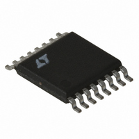
LT1977IFE#TRPBF Linear Technology, LT1977IFE#TRPBF Datasheet - Page 23

LT1977IFE#TRPBF
Manufacturer Part Number
LT1977IFE#TRPBF
Description
IC REG SW 1.5A HV STPDWN 16TSSOP
Manufacturer
Linear Technology
Type
Step-Down (Buck)r
Datasheet
1.LT1977EFEPBF.pdf
(24 pages)
Specifications of LT1977IFE#TRPBF
Internal Switch(s)
Yes
Synchronous Rectifier
No
Number Of Outputs
1
Voltage - Output
1.2 ~ 54 V
Current - Output
1.5A
Frequency - Switching
500kHz
Voltage - Input
3.3 ~ 60 V
Operating Temperature
-40°C ~ 125°C
Mounting Type
Surface Mount
Package / Case
16-TSSOP Exposed Pad, 16-eTSSOP, 16-HTSSOP
Lead Free Status / RoHS Status
Lead free / RoHS Compliant
Power - Output
-
Available stocks
Company
Part Number
Manufacturer
Quantity
Price
APPLICATIO S I FOR ATIO
First, the combination of output capacitor ESR and a large
R
loop gain is not rolled off sufficiently at the switching fre-
quency output ripple will perturb the V
unstable duty cycle switching similar to subharmonic
oscillation. This may not be apparent at the output. Small-
signal analysis will not show this since a continuous time
PACKAGE DESCRIPTIO
C
may stop loop gain rolling off altogether. Second, if the
6.60 ±0.10
U
NOTE:
1. CONTROLLING DIMENSION: MILLIMETERS
2. DIMENSIONS ARE IN
3. DRAWING NOT TO SCALE
(.0035 – .0079)
0.09 – 0.20
4.50 ±0.10
RECOMMENDED SOLDER PAD LAYOUT
U
Information furnished by Linear Technology Corporation is believed to be accurate and reliable.
However, no responsibility is assumed for its use. Linear Technology Corporation makes no represen-
tation that the interconnection of its circuits as described herein will not infringe on existing patent rights.
(.169 – .177)
SEE NOTE 4
4.30 – 4.50*
(.020 – .030)
W
(.141)
0.50 – 0.75
MILLIMETERS
3.58
0.65 BSC
C
(INCHES)
U
pin enough to cause
0.45 ±0.05
16-Lead Plastic TSSOP (4.4mm)
(.116)
(Reference LTC DWG # 05-08-1663)
2.94
1.05 ±0.10
U
Exposed Pad Variation BC
0.25
REF
*DIMENSIONS DO NOT INCLUDE MOLD FLASH. MOLD FLASH
4. RECOMMENDED MINIMUM PCB METAL SIZE
SHALL NOT EXCEED 0.150mm (.006") PER SIDE
FOR EXPOSED PAD ATTACHMENT
0° – 8°
FE Package
system is assumed. If needed, an additional capacitor (C
can be added to form a pole at below the switching frequency
(if R
When checking loop stability the circuit should be oper-
ated over the application’s full voltage, current and tem-
perature range. Any transient loads should be applied and
the output voltage monitored for a well-damped behavior.
C
(.0256)
0.65
BSC
= 26k, C
16 1514 13 12 11
1
(.0077 – .0118)
0.195 – 0.30
2
TYP
C
(.193 – .201)
3 4 5 6 7 8
4.90 – 5.10*
= 1500pF, C
(.141)
3.58
10
9
(.002 – .006)
0.05 – 0.15
FE16 (BC) TSSOP 0204
F
= 330pF).
(.0433)
(.116)
2.94
MAX
1.10
(.252)
6.40
BSC
LT1977
23
1977fa
F
)


