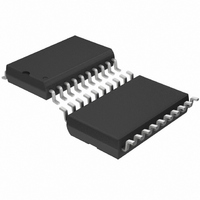
LT1371ISW#TRPBF Linear Technology, LT1371ISW#TRPBF Datasheet - Page 12

LT1371ISW#TRPBF
Manufacturer Part Number
LT1371ISW#TRPBF
Description
IC SWTCHNG REG 3A HI-EFF 20-SOIC
Manufacturer
Linear Technology
Type
Step-Down (Buck), Step-Up (Boost), Inverting, Cuk, Flyback, Forward Converterr
Datasheet
1.LT1371CRPBF.pdf
(16 pages)
Specifications of LT1371ISW#TRPBF
Internal Switch(s)
Yes
Synchronous Rectifier
No
Number Of Outputs
1
Voltage - Output
1.25 ~ 35 V
Current - Output
3A
Frequency - Switching
500kHz
Voltage - Input
2.7 ~ 25 V
Operating Temperature
0°C ~ 70°C
Mounting Type
Surface Mount
Package / Case
20-SOIC (7.5mm Width)
Lead Free Status / RoHS Status
Lead free / RoHS Compliant
Power - Output
-
Available stocks
Company
Part Number
Manufacturer
Quantity
Price
APPLICATIO S I FOR ATIO
LT1371
T7 Package Layout Considerations
Electrical connection to the tab of a T7 package is required
for proper device operation. If the tab is tied directly to the
ground plane (Figure 4) no other considerations are nec-
essary. If the tab is not connected directly to the ground
plane, as in a vertically mounted application, a separate
electrical connection from the tab to a “floating node” is
required. Ground returns for the V
nents and output feedback resistor divider are then con-
nected to the floating node. This is shown schematically in
Figure 7. All other system ground connections are made to
Pin 4.
The electrical connection from the T7 package tab to the
floating node must be a low resistance (< 0.1 ), low
inductance (< 20nH) path which can be accomplished with
a jumper wire or an electrically conductive heat sink.
Bolt the jumper wire directly to the tab using a solder tail
to maintain low resistance. The jumper wire length should
not exceed 3/4 inch of 24 AWG gauge wire or larger to
minimize the inductance.
Vertically mounted electrically conductive heat sinks are
available from many heat sink manufacturers. These heat
sinks also have tabs that solder directly to the board
creating the required low resistance, low inductance path
from the tab to the floating node. The tab should be bolted
12
U U
IN
capacitor, V
W
C
U
compo-
or soldered directly to the heat sink to maintain low
resistance. Heat sinks are available in clip-on styles but are
only recommended if the tab to heat sink contact resis-
tance can be maintained below 0.1
product.
More Help
For more detailed information on switching regulator
circuits, please see Application Note 19. Linear Technol-
ogy also offers a computer software program,
SwitcherCAD, to assist in designing switching converters.
In addition, our Applications Department is always ready
to lend a helping hand.
(TAB TIES INTERNALLY
Figure 7. Tab Connections for Vertically Mounted T7 Package
TO PIN 4 GROUND)
FLOATING NODE
1
V
GND
C
TAB
LT1371T7
V
V
IN
IN
7
GND
V
SW
4
FB
SYSTEM GROUND
5
2
for the life of the
LT1371 • F07
V
OUT


