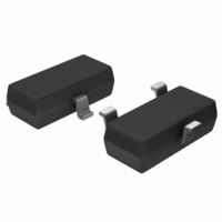
S-8353A30MA-IQPT2G Seiko Instruments, S-8353A30MA-IQPT2G Datasheet - Page 21

S-8353A30MA-IQPT2G
Manufacturer Part Number
S-8353A30MA-IQPT2G
Description
IC REG SW PWM 3.0V SOT23-3
Manufacturer
Seiko Instruments
Type
Step-Up (Boost)r
Datasheet
1.S-8354A33MC-JQST2G.pdf
(49 pages)
Specifications of S-8353A30MA-IQPT2G
Internal Switch(s)
Yes
Synchronous Rectifier
No
Number Of Outputs
1
Voltage - Output
3V
Frequency - Switching
50kHz
Voltage - Input
0.9 ~ 10 V
Operating Temperature
-40°C ~ 85°C
Mounting Type
Surface Mount
Package / Case
SOT-23-3
Power - Output
150mW
Lead Free Status / RoHS Status
Lead free / RoHS Compliant
Current - Output
-
Lead Free Status / Rohs Status
Lead free / RoHS Compliant
Rev.3.0
STEP-UP, PWM CONTROL or PWM / PFM SWITCHABLE BUILT-IN TRANSISTOR SWITCHING REGULATOR
3. Capacitor (C
4. V
A capacitor on the input side (C
current. Select a C
A capacitor on the output side (C
flows intermittently to the load current, so step-up types need a larger capacitance than step-down types. Therefore,
select an appropriate capacitor in accordance with the ripple voltage, which increases in case of a higher output
voltage or a higher load current. The capacitor value should be 10 μF or more.
Select an appropriate capacitor the equivalent series resistance (R
range in this IC depends on the R
m
wiring, and the applications (output load). Therefore, fully evaluate the R
determine the best value.
Refer to the “ 1. Example of Ceramic Capacitor Application ” ( Figure 16 ) in the “
circuit example using a ceramic capacitor and the external resistance of the capacitor (R
The D and J types provides separate internal circuit power supply (VDD pin) and output voltage setting pin (VOUT
pin) in the IC, making it ideal for the following applications.
Choose the products in the Table 18 according to the applications (1) or (2) above.
Cautions 1. This IC starts a step-up operation at V
Connection to VDD pin
Ω
DD
Output voltage (V
(1) When changing the output voltage with external resistance.
(2) When outputting a high voltage within the operating voltage (10 V).
_00
maximizes the characteristics. However, the best R
/ V
S-835xx18
S-835xx50
OUT
2. Choose external resistors R
3. Attach a capacitor (C
Separate Type (D and J Types)
voltage and frequency of the oscillator. (Input a voltage of 1.8 V or more at the VDD pin for all
products with a setting less than 1.9 V.) An input voltage of 1.8 V or more at the VDD pin allows
connection of the VDD pin to either the input voltage VIN pin or output VOUT pin.
is impedance between the VOUT pin and VSS pin in the IC chip.
between the VOUT pin and VSS pin is as follows :
(1) S-835xx18 : 2.1 M Ω to 14.8 M Ω
(2) S-835xx20 : 1.4 M Ω to 14.8 M Ω
(3) S-835xx30 : 1.4 M Ω to 14.2 M Ω
(4) S-835xx50 : 1.4 M Ω to 12.1 M Ω
oscillation of the output voltage occurs. Calculate C
C
IN
C
, C
[ ]
IN
F
CC
value according to the impedance of the power supply used.
L
=
)
)
2
•
π
•
1.8 V ≤ V
R
Table 18
A
IN
1
V
•
) improves the efficiency by reducing the power impedance and stabilizing the input
IN
L
ESR
20
) is used for smoothing the output voltage. For step-up types, the output voltage
Yes
C
or V
−
) in parallel to the R
. Although the inductance value (L value) is also a factor, an R
kHz
CC
CC
< 5 V
A
Seiko Instruments Inc.
and R
B
5 V ≤ V
so as to not affect the output voltage, considering that there
DD
Yes
A
ESR
V
= 0.8 V, but set 1.8 ≤ V
CC
−
resistance when an unstable event such as
IN
≤ 10 V
value may depend on the L value, the capacitance, the
ESR
) for stable output voltage. The stable voltage
C
using the following equation :
ESR
under the actual operating conditions to
DD
≤ 10 V to stabilize the output
ESR
Application Circuit ” for the
S-8353/8354 Series
).
The internal resistance
ESR
of 30 t o 500
21


