MAX619CPA Maxim Integrated Products, MAX619CPA Datasheet
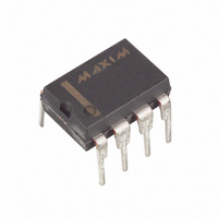
IC CONV DCDC 5V CH/PUMP 8-DIP

MAX619CPA

Manufacturer Part Number
MAX619CPA
Description
IC CONV DCDC 5V CH/PUMP 8-DIP
Manufacturer
Maxim Integrated Products
Type
Switched Capacitor (Charge Pump)r
Datasheet

Specifications of MAX619CPA

Internal Switch(s)
Yes
Synchronous Rectifier
No
Number Of Outputs
1
Voltage - Output
5V
Current - Output
50mA
Frequency - Switching
500kHz
Voltage - Input
2 ~ 3.6 V
Operating Temperature
0°C ~ 70°C
Mounting Type
Through Hole
Package / Case
8-DIP (0.300", 7.62mm)
Power - Output
727mW
Function
Step Up
Output Voltage
5 V
Output Current
50 mA
Maximum Operating Temperature
+ 70 C
Minimum Operating Temperature
0 C
Mounting Style
Through Hole
Lead Free Status / RoHS Status
Contains lead / RoHS non-compliant
The MAX619 step-up charge-pump DC-DC converter
delivers a regulated 5V ±4% output at 50mA over tem-
perature. The input voltage range is 2V to 3.6V (two
battery cells).
The complete MAX619 circuit fits into less than 0.1in
board space because it requires only four external
capacitors: two 0.22 F flying capacitors, and 10 F
capacitors at the input and output.
Low operating supply current (150 A max) and low
shutdown supply current (1 A max) make this device
ideal for small, portable, and battery-powered applica-
tions. When shut down, the load is disconnected from
the input.
The MAX619 is available in 8-pin DIP and SO packages.
________________________Applications
19-0227; Rev 2; 5/96
For free samples & the latest literature: http://www.maxim-ic.com, or phone 1-800-998-8800
__________________Pin Configuration
_______________General Description
TOP VIEW
Two Battery Cells to 5V Conversion
Local 3V-to-5V Conversion
Portable Instruments & Handy-Terminals
Battery-Powered Microprocessor-Based Systems
5V Flash Memory Programmer
Minimum Component DC-DC Converters
Remote Data-Acquisition Systems
Compact 5V Op-Amp Supply
Regulated 5V Supply from Lithium Backup Battery
Switching Drive Voltage for MOSFETs in
Low-Voltage Systems
OUT
C1+
C2+
IN
________________________________________________________________ Maxim Integrated Products
1
2
3
4
MAX619
DIP/SO
8
7
6
5
C1-
SHDN
GND
C2-
Regulated 5V Charge-Pump
2
of
____________________________Features
_______________Ordering Information
* Dice are specified at T
__________Typical Operating Circuit
MAX619CPA
MAX619CSA
MAX619C/D
MAX619EPA
MAX619ESA
MAX619MJA
Regulated 5V ±4% Charge Pump
Output Current Guaranteed over Temperature
2V to 3.6V Input Range
No Inductors; Very Low EMI Noise
Ultra-Small Application Circuit (0.1in
Uses Small, Inexpensive Capacitors
500kHz Internal Oscillator
Logic-Controlled 1 A Max Shutdown
Supply Current
Shutdown Disconnects Load from Input
8-Pin DIP and SO Packages
20mA (V
50mA (V
PART
2V to 3.6V
INPUT
0.22 F
ON/OFF
10 F
IN
IN
DC-DC Converter
≥ 2V)
≥ 3V)
-40°C to +85°C
-40°C to +85°C
-55°C to +125°C
TEMP. RANGE
0°C to +70°C
0°C to +70°C
0°C to +70°C
A
IN
C1+
C1-
SHDN
= +25 °C.
MAX619
GND
OUT
C2+
C2-
PIN-PACKAGE
8 Plastic DIP
8 SO
Dice*
8 Plastic DIP
8 SO
8 CERDIP
10 F
2
0.22 F
)
5V, 20mA
OUTPUT
1

Related parts for MAX619CPA

MAX619CPA Summary of contents

Page 1

... Ultra-Small Application Circuit (0.1in Uses Small, Inexpensive Capacitors 500kHz Internal Oscillator Logic-Controlled 1 A Max Shutdown Supply Current Shutdown Disconnects Load from Input 8-Pin DIP and SO Packages _______________Ordering Information PART MAX619CPA MAX619CSA MAX619C/D MAX619EPA MAX619ESA MAX619MJA * Dice are specified at T __________Typical Operating Circuit INPUT ...

Page 2

Regulated 5V Charge-Pump DC-DC Converter ABSOLUTE MAXIMUM RATINGS V to GND ............................................................-0.3V to +5. GND .........................................................-0.3V to +5.5V OUT SHDN to GND ..............................................-0. Continuous (Note 1)..................................................120mA OUT Continuous Power Dissipation (T = +70°C) A ...

Page 3

Operating Characteristics (T = +25°C, unless otherwise noted.) A EFFICIENCY vs. OUTPUT CURRENT AND INPUT VOLTAGE 3.6V ...

Page 4

Regulated 5V Charge-Pump DC-DC Converter _____________________Pin Description PIN NAME FUNCTION 1 C1+ Positive Terminal for Input Supply Voltage +5V Output Voltage when in OUT 3 OUT shutdown mode. 4 C2+ Positive Terminal for C2 ...

Page 5

IN C3 10µF * S1A C2+ S2A C2 0.22µF S1B C2- C1+ S2B S1C C1 0.22µF S2C C1- S1D * SWITCHES SHOWN IN TRIPLER MODE, DISCHARGE CYCLE Figure 1. Block Diagram ________________________________________________________________________________________ Regulated 5V Charge-Pump DC-DC Converter P IC POWER ...

Page 6

Regulated 5V Charge-Pump DC-DC Converter __________Applications Information Capacitor Selection Charge-Pump Capacitors C1 and C2 The values of charge-pump capacitors C1 and C2 are critical to ensure adequate output current and avoid excessive peak currents. Use values in the range of ...

Page 7

Layout Considerations The MAX619’s high oscillator frequency makes good layout important. A good layout ensures stability and helps maintain the output voltage under heavy loads. For best performance, use very short connections to the capacitors. Paralleling Devices Two MAX619s can ...

Related keywords