IRU3065CLTR International Rectifier, IRU3065CLTR Datasheet - Page 11
IRU3065CLTR
Manufacturer Part Number
IRU3065CLTR
Description
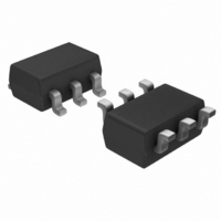
IC POS-NEG DC-DC CNTRLR SOT23-6
Manufacturer
International Rectifier
Type
Invertingr
Specifications of IRU3065CLTR
Internal Switch(s)
No
Synchronous Rectifier
No
Number Of Outputs
1
Voltage - Output
Adjustable
Current - Output
1A
Frequency - Switching
Adj to 1.5MHz
Voltage - Input
5V
Operating Temperature
0°C ~ 70°C
Mounting Type
Surface Mount
Package / Case
SOT-23-6
Power - Output
240mW
For Use With
IRDC3065 - LOW PWR SWTCH REG REF DESIGN KIT
Lead Free Status / RoHS Status
Contains lead / RoHS non-compliant
Available stocks
Company
Part Number
Manufacturer
Quantity
Price

Part Number:
IRU3065CLTRPBF
Manufacturer:
IR
Quantity:
20 000


Power Limit Mode
switching period continuous decreases until the induc-
tor current goes into the boundary of discontinuous and
continuous mode as shown in Figure 21. Then the
IRU3065 controlled buck boost converter goes into power
limit mode. In this mode, the output power is limited.
The output voltage is no longer regulated. The output
voltage decreases when the load current increases as
shown in Figure 19. In this mode, the shaded inductor
current in Figure 18 keeps same. The turn off time pe-
riod is dependent on the output voltage. When the out-
put current increases, the output voltage decreases and
it takes more time for the inductor current to reset from
peak current to zero. Therefore, the turn off period in-
creases. Overall the switching frequency decreases
when load current increases as shown in Figure 20.
Output diode
current
Output of current
comparator
When the output current continuous increases, the
Figure 21 - Operation waveforms of IRU3065 con-
Voltage across
the inductor
Inductor
current
trolled buck boost converter at power limit mode.
R
R
V
3
2
out
V
Vin
ref
V
Vgate
I
V
peak
out
D
I
out
t
on
T
s
t
1
www.irf.com
Influence of System Parameters
I
output voltage is out of the regulation and switching fre-
quency starts to decreases. When output current equals
I
sis shows that the current I
f
rent sensing resistor R
input and output voltage.
Figure 22 shows the calculated output voltage versus
output current with different current sensing resistor R
With different R
the power process ability changes. Figure 23 shows
the calculated operation switching frequency versus
output current with different inductance L when R
The inductance L determines the maximum switching
frequency of the buck boost converter.
Figure 23 - Theoretical operation switching frequency
f s I out 1 H
f s I out 1.1 H
f s I out 1.2 H
OCP
OCP
S(MAX)
V out I out 0.1
V out I out 0.11
V out I out 0.12
From above section, there is a critical output current
Figure 22 - Theoretical output voltage versus output
versus output current with different inductance L.
current with different current sensing resistor R
. When the output current is larger than I
, the frequency reaches its maximum f
4.583 10
1.3 10
strongly depends on the parameters such as cur-
0.452
6
4
1.5 10
1.2 10
9 10
6 10
3 10
5
0.02
6
6
5
5
5
6
5
4
3
2
1
0
0
0.02
0
0
S
, the critical current IOCP varies, and
0.1
0.1
S
and inductance L as well as the
0.2
0.2
OCP
IRU3065(PbF)
and maximum frequency
0.3
0.3
I out
I out
0.4
0.4
0.5
0.5
S(MAX)
OCP
. Analy-
S
0.6
0.6
=0.1Ω.
, the
11
S.
0.7
0.7
S
0.7
0.7
.
Related parts for IRU3065CLTR
Image
Part Number
Description
Manufacturer
Datasheet
Request
R

Part Number:
Description:
Positive To Negative Dc To Dc Controller
Manufacturer:
International Rectifier Corp.
Datasheet:
Part Number:
Description:
SCHOTTKY RECTIFIER
Manufacturer:
International Rectifier Corp.
Datasheet:
Part Number:
Description:
SCHOTTKY RECTIFIER
Manufacturer:
International Rectifier Corp.
Datasheet:
Part Number:
Description:
SCHOTTKY RECTIFIER
Manufacturer:
International Rectifier Corp.
Datasheet:
Part Number:
Description:
SCHOTTKY RECTIFIER
Manufacturer:
International Rectifier Corp.
Datasheet:
Part Number:
Description:
SCHOTTKY RECTIFIER
Manufacturer:
International Rectifier Corp.
Datasheet:
Part Number:
Description:
SCHOTTKY RECTIFIER
Manufacturer:
International Rectifier Corp.
Datasheet:
Part Number:
Description:
SCHOTTKY RECTIFIER
Manufacturer:
International Rectifier Corp.
Datasheet:
Part Number:
Description:
SCHOTTKY RECTIFIER
Manufacturer:
International Rectifier Corp.
Datasheet:
Part Number:
Description:
SCHOTTKY RECTIFIER
Manufacturer:
International Rectifier Corp.
Datasheet:
Part Number:
Description:
SCHOTTKY RECTIFIER
Manufacturer:
International Rectifier Corp.
Datasheet:
Part Number:
Description:
SCHOTTKY RECTIFIER
Manufacturer:
International Rectifier Corp.
Datasheet:
Part Number:
Description:
SCHOTTKY RECTIFIER
Manufacturer:
International Rectifier Corp.
Datasheet:
Part Number:
Description:
SCHOTTKY RECTIFIER
Manufacturer:
International Rectifier Corp.
Datasheet:
Part Number:
Description:
SCHOTTKY RECTIFIER
Manufacturer:
International Rectifier Corp.
Datasheet: