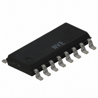
IL717-3E NVE, IL717-3E Datasheet

IL717-3E
Specifications of IL717-3E
IL717-3E
Q2491583A
Related parts for IL717-3E
IL717-3E Summary of contents
Page 1
... ADCs and DACs, parallel buses and peripheral interfaces. The IL715, IL716, and IL717 are available in 0.3" and 0.15" 16-pin SOIC packages and performance is specified over the temperature range of −40°C to +100°C without derating. The IL715T, IL716T, and IL717T are specified over − ...
Page 2
... Package Power Dissipation Safety and Approvals IEC61010-1 TUV Certificate Numbers: N1502812, N1502812-101 Classification as Reinforced Insulation Model IL715, IL716, and IL717 IL715-3, IL716-3, and IL717-3 UL 1577 Component Recognition Program File Number: E207481 Rated 2500V for 1 minute RMS Soldering Profile Per JEDEC J-STD-020C, MSL=2 Symbol Min ...
Page 3
... DD 9 GND Ground Return for connection 11 IN Data in, channel Data in, channel OUT Data out, channel OUT Data out, channel GND Ground Return for Supply voltage DD2 IL715/IL716/IL717 V DD1 GND GND 1 IL715 V DD1 GND OUT 3 OUT 4 NC GND 1 IL716 3 V DD2 GND ...
Page 4
... IL717 Pin Connections 1 V Supply voltage DD1 2 GND Ground return for Data in, channel Data in, channel Data in, channel OUT Data out, channel connection 8 GND Ground return for GND Ground return for connection 11 IN Data in, channel OUT Data out, channel OUT Data out, channel 2 ...
Page 5
... Switching Specifications 100 110 PHL t 12 PLH PWD PSK |CM |,| CSK 140 (8) Magnetic Field Immunity (V = 3V, 3V<V DD2 H 1000 1500 PF H 1800 2000 PM H 1800 2000 OSC K 2 IL715/IL716/IL717 Max. Units Test Conditions 20 µ µA = −20 µ − µ Mbps 50% Points ...
Page 6
... DD2 H 2800 3500 PF H 4000 4500 PM H 4000 4500 OSC K 2.5 X and/or t between devices at 25°C. PHL PLH < 0.8 V. The common mode voltage slew rates apply to both rising O 6 IL715/IL716/IL717 Max. Units Test Conditions 30 µ µA = −20 µ −4 mA ...
Page 7
... This has obvious advantages over optocouplers, which have power consumption heavily dependent on mark-to-space ratio. IL715/IL716/IL717 Power Supply Decoupling Both power supplies to these devices should be decoupled with low ESR 47 nF ceramic capacitors. Ground planes for both GND GND are highly recommended for data rates above 10 Mbps ...
Page 8
... This circuit illustrates a typical single-channel delta-sigma ADC. The A/D is located on the bridge with no signal conditioning electronics between the bridge sensor and the ADC. In this case, the IL717 is the best choice for isolation. It isolates the control bus from the microcontroller. The system clock is located on the isolated side of the system. ...
Page 9
... NOTE: Pin spacing is a BASIC dimension; tolerances do not accumulate 9 IL715/IL716/IL717 NOM 0.054 (1.4) 0.072 (1.8) 0.004 (0.1) 0.012 (0.3) 0.287 (7.29) 0.300 (7.62) NOM 0.016 (0.4) 0.050 (1.3) 0.040 (1.0) ...
Page 10
... Blank = Standard T = High Temperature Base Part Number 715 = 4 Drive Channels 716 = 2 Drive Channels 2 Receive Channels 717 = 3 Drive Channels 1 Receive Channel Product Family IL = Isolators 10 IL715/IL716/IL717 IL716 IL717 IL716E IL717E IL716-3 IL717-3 IL716-3E IL717-3E IL716T IL717T IL716TE IL717TE IL716T-3 IL717T-3 IL716T-3E IL717T-3E RoHS COMPLIANT ...
Page 11
... IEC 61010-1 Classification: “Reinforced Insulation” added. • Dynamic Power Consumption: units corrected from mA/mHz to mA/MHz. • Ordering Information. 5 Volt only option removed. The following valid part numbers removed. IL715B, IL715-3B, IL715BE, IL715-3BE IL716B, IL716-3B, IL716BE, IL716-3BE IL717B, IL717-3B, IL717BE, IL717-3BE 11 IL715/IL716/IL717 ...
Page 12
... NVE Corporation. NVE Corporation does not authorize, nor warrant, any NVE Corporation product for use in life support devices or systems or other critical applications without the express written approval of the President of NVE Corporation. Specifications shown are subject to change without notice. ISB-DS-001-IL715/6/7-R November 2009 IL715/IL716/IL717 12 ...


