FOD3150 Fairchild Optoelectronics Group, FOD3150 Datasheet - Page 6
FOD3150
Manufacturer Part Number
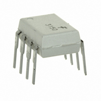
FOD3150
Description
OPTOCOUPLER GATE DRV 1A 8-DIP
Manufacturer
Fairchild Optoelectronics Group
Series
OPTOPLANAR®r
Datasheet
1.FOD3150.pdf
(19 pages)
Specifications of FOD3150
Voltage - Isolation
5000Vrms
Number Of Channels
1, Unidirectional
Current - Output / Channel
1.5A
Propagation Delay High - Low @ If
275ns @ 7mA ~ 16mA
Current - Dc Forward (if)
25mA
Input Type
DC
Output Type
Gate Driver
Mounting Type
Through Hole
Package / Case
8-DIP (0.300", 7.62mm)
Lead Free Status / RoHS Status
Lead free / RoHS Compliant
Available stocks
Company
Part Number
Manufacturer
Quantity
Price

Part Number:
FOD3150
Manufacturer:
FAIRCHILD/仙童
Quantity:
20 000
Part Number:
FOD3150(SG)
Manufacturer:
FAIRCHILD/仙童
Quantity:
20 000
Part Number:
FOD3150A
Manufacturer:
FAIRCHILD/仙童
Quantity:
20 000
Company:
Part Number:
FOD3150ASD
Manufacturer:
AD
Quantity:
1 400
Part Number:
FOD3150ASD
Manufacturer:
ON/安森美
Quantity:
20 000
Part Number:
FOD3150S
Manufacturer:
FAIRCHILD/仙童
Quantity:
20 000


©2008 Fairchild Semiconductor Corporation
FOD3150 Rev. 1.0.3
Switching Characteristics
Apply over all recommended conditions, typical value is measured at V
unless otherwise specified.
Notes:
1. Maximum pulse width = 10µs, maximum duty cycle = 0.2%
2. Derate linearly above 87°C, free air temperature at a rate of 0.77mW/°C
3. No derating required across temperature range.
4. Functional operation under these conditions is not implied. Permanent damage may occur if the device is
5. Device is considered a two terminal device: Pins 2 and 3 are shorted together and Pins 5, 6, 7 and 8 are shorted
6. 5,000 V
7. The difference between t
8. Common mode transient immunity at output high is the maximum tolerable negative dVcm/dt on the trailing edge of
9. Common mode transient immunity at output low is the maximum tolerable positive dVcm/dt on the leading edge of
t
Symbol
t
subjected to conditions outside these ratings.
together.
the common mode impulse signal, Vcm, to assure that the output will remain high (i.e. V
the common pulse signal, Vcm, to assure that the output will remain low (i.e. V
UVLO OFF
UVLO ON
(Skew)
| CM
| CM
PWD
PDD
t
t
PHL
PLH
t
t
r
f
H
L
|
|
RMS
Propagation Delay Time to Logic
Low Output
Propagation Delay Time to Logic
High Output
Pulse Width Distortion,
| t
Propagation Delay Difference
Between Any Two Parts or
Channels, (t
Output Rise Time (10% – 90%)
Output Fall Time (90% – 10%)
UVLO Turn On Delay
UVLO Turn Off Delay
Common Mode Transient
Immunity at Output High
Common Mode Transient
Immunity at Output Low
for 1 minute duration is equivalent to 6,000 VAC
PHL
– t
PLH
Parameter
PHL
|
PHL
– t
and t
PLH
)
PLH
(7)
between any two FOD3150 parts under same test conditions.
I
Rg = 20 , Cg =10nF,
f = 10kHz, Duty Cycle = 50%
I
I
T
I
T
V
F
F
F
F
A
A
CM
= 7mA to 16mA,
= 10mA , V
= 10mA , V
= 7 to 16mA, V
= 25°C, V
= 25°C, V
= 2000V
Conditions
6
CC
CC
O
O
(9)
RMS
> 5V
< 5V
= 30V,
= 30V, V
CM
for 1 second duration.
= 2000V
CC
F
= 30V, V
= 0V,
(8)
O
< 1.0V).
EE
Min.
-350
100
100
= Ground, T
20
20
O
> 15.0V).
Typ.
275
255
1.6
0.4
20
60
60
50
50
A
= 25°C
Max.
500
500
300
350
www.fairchildsemi.com
Units
kV/µs
kV/µs
ns
ns
ns
ns
ns
ns
µs
µs
Related parts for FOD3150
Image
Part Number
Description
Manufacturer
Datasheet
Request
R

Part Number:
Description:
LED 7-SEG SGL CC RED RHDP .3"
Manufacturer:
Fairchild Optoelectronics Group
Datasheet:

Part Number:
Description:
LED IR EMITTING 940NM SIDELOOKER
Manufacturer:
Fairchild Optoelectronics Group
Datasheet:

Part Number:
Description:
LED IR EMITTING GAAS 940NM 3MM
Manufacturer:
Fairchild Optoelectronics Group
Datasheet:
Part Number:
Description:
LED IR EMITTING ALGAAS 880NM 3MM
Manufacturer:
Fairchild Optoelectronics Group
Datasheet:
Part Number:
Description:
LED IR EMITTING 940NM SMD 2MM
Manufacturer:
Fairchild Optoelectronics Group
Datasheet:
Part Number:
Description:
IC PHOTOTRANS IR 940NM BLK 1.9MM
Manufacturer:
Fairchild Optoelectronics Group
Datasheet:
Part Number:
Description:
LED IR GAAS SIDELOOK 940NM
Manufacturer:
Fairchild Optoelectronics Group
Datasheet:
Part Number:
Description:
LED IR EMITTING 940NM 2MM SMD
Manufacturer:
Fairchild Optoelectronics Group
Datasheet:
Part Number:
Description:
IC PHOTOTRANS IR 940NM 1.9MM GW
Manufacturer:
Fairchild Optoelectronics Group
Datasheet:
Part Number:
Description:
LED IR EMITTING 880NM 2-PLCC
Manufacturer:
Fairchild Optoelectronics Group
Datasheet:
Part Number:
Description:
LED 7-SEG SGL CC RED RHDP .3"
Manufacturer:
Fairchild Optoelectronics Group
Datasheet:

Part Number:
Description:
DIODE EMITTING GAAS IRED TO-46
Manufacturer:
Fairchild Optoelectronics Group
Datasheet:
Part Number:
Description:
DIODE EMITTING GAAS IRED TO-46
Manufacturer:
Fairchild Optoelectronics Group
Datasheet:

Part Number:
Description:
LED SS BIPO RED/GRN DIFF PCB 5MM
Manufacturer:
Fairchild Optoelectronics Group
Datasheet:

Part Number:
Description:
LED SS HI EFF GREEN DIFF 3MM
Manufacturer:
Fairchild Optoelectronics Group
Datasheet: