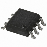
ACPL-072L-000E Avago Technologies US Inc., ACPL-072L-000E Datasheet

ACPL-072L-000E
Specifications of ACPL-072L-000E
ACPL-072L-000E
Available stocks
Related parts for ACPL-072L-000E
ACPL-072L-000E Summary of contents
Page 1
... Multiplexed Data Transmission L • General Instrument and Data Acquisition • Computer Peripheral interface • Microprocessor System Interface for 1 min. per UL1577 for ACPL-772L rms for 1 min. per UL1577 for ACPL-072L rms = 630 V for ACPL-772L Option 060 peak = 560 V for ACPL-072L Option 060 ...
Page 2
... To order, choose a part number from the part number column and combine with the desired option from the option column to form an order entry. Example 1: ACPL-772L-560E to order product of Gull Wing Surface Mount package in Tape and Reel packaging with IEC/EN/DIN EN 60747-5-2 Safety Approval in RoHS compliant. Example 2: ACPL-072L to order product of Small Outline SO-8 package in tube packaging and non RoHS compliant ...
Page 3
... TYPE NUMBER XXXXV YYWW 1.19 (0.047) MAX. 3.56 ± 0.13 (0.140 ± 0.005) 1.080 ± 0.320 (0.043 ± 0.013) ACPL-772L Package with Gull Wing Surface Mount Option 300 9.65 ± 0.25 (0.380 ± 0.010 1.19 (0.047) MAX. 1.080 ± 0.320 (0.043 ± ...
Page 4
... ACPL-072L Small Outline SO-8 Package XXXV 3.937 ± 0.127 YWW (0.155 ± 0.005 PIN ONE 0.406 ± 0.076 (0.016 ± 0.003) * 5.080 ± 0.127 (0.200 ± 0.005) 3.175 ± 0.127 (0.125 ± 0.005) TOTAL PACKAGE LENGTH (INCLUSIVE OF MOLD FLASH) * 5.207 ± 0.254 (0.205 ± 0.010) DIMENSIONS IN MILLIMETERS (INCHES) ...
Page 5
... 150 ˚ C smax smin Note: Non-halide flux should be used Regulatory Information Both ACPL-072L and ACPL-772L are approved by the following organizations: IEC/EN/DIN EN 60747-5-2 Approved under: IEC 60747-5-2:1997 + A1:2002 EN 60747-5-2:2001 + A1:2002 DIN EN 60747-5-2 (VDE 0884 Teil 2):2003-01. (option 060 only) 5 PEAK TEMP. ...
Page 6
... S, INPUT P R Value ACPL- 772L ACPL-072L Units 7.1 4.9 mm 7.4 4.8 mm 0.08 0.08 mm >175 >175 V IIIa IIIa ACPL-772L ACPL-072L Option 060 Option 060 I – – – – III I – III 55/105/21 55/105/ 630 560 IORM 1181 1050 PR 945 840 PR 6000 4000 ...
Page 7
Table 3. Absolute Maximum Ratings Parameter Storage Temperature [1] Ambient Operating Temperature Supply Voltages Input Voltage Output Voltage Average Output Current Lead Solder Temperature Solder Reflow Temperature Profile Table 4. Recommended Operating Conditions Parameter Ambient Operating Temperature Supply Voltages ( ...
Page 8
Table 6. Switching Specifications Test conditions that are not specified can be anywhere within the recommended operating range. The following specifications cover the following power supply combinations: (4.5V≤V (3V≤V ≤3.6V, 3V≤V ≤3.6V), (4.5V≤V DD1 DD2 All typical specifications are at ...
Page 9
... Device considered a two-terminal device: pins and 4 shorted together and pins and 8 shorted together. 10. In accordance with UL1577, each ACPL-072L is proof tested by applying an insulation test voltage ≥ 4500 V ≤ 5 mA). Each ACPL-772L is proof tested by applying an insulation test voltage ≥ 4500 V ...
Page 10
... PWD can be expressed in percent by dividing the PWD (in ns) by the minimum pulse width (in ns) being transmitted. Typically, PWD on the order of 20-30% of the minimum pulse width is tolerable. The PWD specification for ACPL-x72L is 6ns (15%) maximum across recommended operating conditions 0.01 µ ...
Page 11
... The ACPL-x72L optocoupler offers the advantage of guaranteed specifications for propagation delays, pulse- width distortion, and propagation delay skew over the recommended temperature and power supply ranges ...


