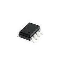
HCPL-2300-360E Avago Technologies US Inc., HCPL-2300-360E Datasheet - Page 11

HCPL-2300-360E
Manufacturer Part Number
HCPL-2300-360E
Description
OPTOCOUPLER 8MBD VDE 8-SMD GW
Manufacturer
Avago Technologies US Inc.
Datasheet
1.HCPL-2300-000E.pdf
(14 pages)
Specifications of HCPL-2300-360E
Package / Case
8-SMD Gull Wing
Voltage - Isolation
3750Vrms
Number Of Channels
1, Unidirectional
Current - Output / Channel
25mA
Data Rate
8MBd
Propagation Delay High - Low @ If
110ns @ 500µA ~ 750µA
Current - Dc Forward (if)
5mA
Input Type
DC
Output Type
Open Collector
Mounting Type
Surface Mount, Gull Wing
Isolation Voltage
3750 Vrms
Maximum Continuous Output Current
25 mA
Maximum Fall Time
20 ns
Maximum Forward Diode Current
5 mA
Maximum Rise Time
40 ns
Minimum Forward Diode Voltage
1 V
Output Device
Logic Gate Photo IC
Configuration
1 Channel
Maximum Baud Rate
8 MBps
Maximum Forward Diode Voltage
1.5 V
Maximum Reverse Diode Voltage
3 V
Maximum Power Dissipation
40 mW
Maximum Operating Temperature
+ 85 C
Minimum Operating Temperature
- 40 C
Number Of Elements
1
Baud Rate
8Mbps
Forward Voltage
1.5V
Forward Current
5mA
Output Current
25mA
Package Type
PDIP SMD
Operating Temp Range
-40C to 85C
Power Dissipation
40mW
Propagation Delay Time
200ns
Pin Count
8
Mounting
Surface Mount
Reverse Breakdown Voltage
3V
Operating Temperature Classification
Industrial
Lead Free Status / RoHS Status
Lead free / RoHS Compliant
Lead Free Status / RoHS Status
Lead free / RoHS Compliant, Lead free / RoHS Compliant
Available stocks
Company
Part Number
Manufacturer
Quantity
Price
Company:
Part Number:
HCPL-2300-360E
Manufacturer:
AVAGO
Quantity:
40 000
Part Number:
HCPL-2300-360E
Manufacturer:
AVAGO/安华高
Quantity:
20 000
Figure 12. Recommended shunt drive circuit for interfacing between TTL/LSTTL/CMOS logic systems.
11
Figure 11. Thermal derating curve, dependence
of safety limiting value with case temperature
per IEC/EN/DIN EN 60747-5-2.
HCPL-2300/
HCPL-0300
A recommended layout for use with an internal 1000 Ω
resistor or an external pull-up resistor and required V
bypass capacitor is given in Figure 19. V
an external pull-up resistor for output voltage levels (V
greater than or equal to 5 V. As illustrated in Figure 19, an
optional V
input and the output leads of the HCPL-2300/HCPL-0300
to provide additional noise immunity at the compromise
of insulation capability (V
CC
and GND trace can be located between the
I-O
).
CC1
is used with
O
CC
)


